Tool Manager
Tools tab

File group
Open File — Opens a file selection window, enabling you to select a tool file to load.
Recent — When clicked, displays a short list of tool files that have been opened recently for you to select.
New File — This button opens a new tool file.
Save File — This button saves the current tool file.
Save As — This button opens a Save As window enabling you to save the current tool file under any name you choose.
Add group
Mill — This button creates a Mill tool. You can then edit the tool to your preferences.
Hole Making — This button creates a Hole Making tool. You can then edit the tool to your preferences.
Turn — This button creates a Turn tool. You can then edit the tool to your preferences.
Edit group
Undo — Use this command button to “undo” changes made in the Tool Manager. The button will be grayed out until a change is made in the Tool Manager. Once a change is made, the button will display as shown here. Click on the button to “undo” the last change made to the Tool Manager. Click on the button again to “undo” the next to the last change and so on. There is no limit to the number of changes that you can “undo”.
Redo — Use this command button to “redo” changes that you have used the Undo feature on. The button will be grayed out until the Undo feature is used. Once the Undo feature is used, the button will display as shown here. Click on the button to “redo” the last “undo”. Click on the button again to “undo” the next to the last “undo” and so on. There is no limit to the number of “undo” actions that you can “redo”.
Auto Gage — Use this button to have Optimizer calculate the highest point on the Z-axis of the tool and uses it for the Gage Point whenever a tool component is modified. This feature only applies to milling tools.
Auto Driven Point — Use this button to have Optimizer calculate the driven point value whenever a tool component is modified. On the Tool Manager Tool Information tab, select the Driven Point record having the value that needs to be adjusted and then click on the Auto Driven Point button. Optimizer will calculate and adjust the values in the Driven Point record to reflect the tip of the tool.
Annotate group
 Annotate Tool — Displays default dimensions for each tool listed in Tool Manager.
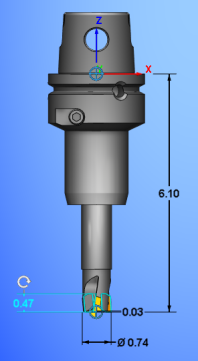
 Save Custom View — Allows dimensional changes and a View orientation to be saved for that specific tool.
 Remove Custom View — Deletes any dimensional changes and View orientation, setting the dimension display back to default.
Help group
Tool Manager Help — This button opens the Help directly to the Tool Manager section.
View tab

Lock Spin Center — This button toggles on and off a lock for the spin center. When the lock is on, the spin center cannot be adjusted by any user. The lock must be toggled off before the spin center can be adjusted again.
Snap to Orthogonal View — Clicking this button resets the view of the tool so that it faces the viewer perfectly. It is as useful way to return to a simple view presentation after spinning or rotating the tool multiple times.
Reverse — This button simply reverses the view of the currently selected tool.
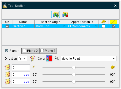
Section — The features on the Section window enables you to define section planes through a model in a workpiece view. You can also define a section wedge through a model in a workpiece view.
-
 Create New Section Plane — Produces a new section plane in the Section window.
 -
 Delete Selected Section Plane — Removes the highlighted section plane from the Section window.
 -
Section table
-
On — Toggle this feature on (checked) to display the section in the View window.
-
Name — Use this field to edit the name of the section.
-
Section Origin — Use this pulldown menu to specify the origin point of the section plane.
-
Apply Section to — This pulldown menu is used to specify what objects are sectioned. The options are:
-
All Children — sections all components beginning with the chosen component, and all children attached to it.
-
Self Only — sections only the chosen component.
-
All Components — sections all components.
-
All Stocks — sections all and only “Stock” type components.
-
-
View — Use this pulldown menu to determine which View windows the section will be displayed in. All Views is the default.
-
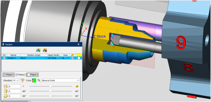
Wedge — Toggle this feature on (checked) to change the section plane into a section wedge. Wedges are formed at the intersection of two or more section planes. Rather than each section plane removing all material, once Wedge is toggled on (checked) the section planes will act as if they stop at the point where they meet rather than continuing through. For instance, in the picture below, if the Wedge option was not on, there would only be ¼ of the stock shown as the other ¾ would have been removed. As you can see though, with the Wedge option on, only ¼ of the stock has been removed and the other ¾ is visible instead.
-
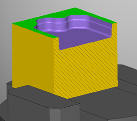
Cross-hatching — Toggle this feature on (checked) to show cross-hatching as show below.
-
Section plane toggles
The Section window can create up to 3 section planes per each section that is created. These individual planes can be toggled on (checked) or off (not checked) in this part of the Section window. All active section planes associated with the section event are applied or removed via the section event “On” toggle. The section plane toggles also work as tabs where the features of the planes can be fine tuned to your liking using the following features: -
Direction — This pulldown menu controls the section plane orientation and direction, and which portion of the section object(s) is removed. Directions are relative to origin of the Component selected in the section table. Options for orientation include: X+, X-, Y+, Y-, Z+, and Z-.
-
Flip Plane — This feature reverses the section direction and removes the opposite portion of the section object(s).
-
Color — Use the Color Palette icon to specify colors for Section.
The right side of the (Color Palette) icon shows the current color of the entity. To change the color of the entity, click on the (Color Palette) icon to display the color palette window shown below.
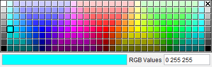
Click on a color in the color palette window, to specify the color for the entity. The color palette will close and the right side of the (Color Palette) icon will update to reflect the selected color.
To close the color palette window without changing the color, click on the in the upper right corner of the color palette.
 -
Pick a point — Clicking the Selection Arrow activates the chosen mode to be used on subsequent section selections. Selection modes are modal, used for repeated picking until a different mode is chosen. Exit selection mode by choosing the selection arrow again, or closing the Section window. The following selection modes are available:
-
Move to Point — applies current section plane/orientation through point selected on a model.
-
Move to Point and Rotate to Normal — as above, plus orients the section plane to be normal to the selected model surface.
-
Move to Vertex — applies section plane/orientation through a vertex point selected on a model.
-
Move to Vertex and Rotate to Normal — as above, plus orients the section plane to be normal to the selected model surface.
-
Align to Parallel Axis — defines section plane to pass through (2) selected parallel cylinder/cone axes.
-
Move to Axis — defines a section plane that passes through a selected cylinder/cone axis.
-
Distance slider — This slider controls distance based from the origin of Component selected in the section table. Section plane distance can be quickly adjusted using the corresponding slider, or by entering a value in the number field. Section plane distances are limited to the extent of the objects they are sectioning.
-
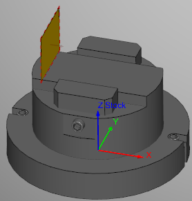
Max — this icon at the far left of the Distance slider to produce the greatest section possible. Only a thin sliver of the material will be left visible as shown below.
-
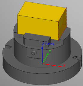
Min — this icon at the far right of the Distance slider the produce the smallest section possible. Only a thin sliver of material will be removed as shown below.
-
Rotation slider — These sliders control rotation based from the origin of Component selected in the section table. Section plane rotation angle can be changed using the corresponding sliders, or by entering values in the corresponding number fields.
ZX View — This automatically sets the currently selected tool to a view that is oriented along the ZX axis.
XZ View — This automatically sets the currently selected tool to a view that is oriented along the XZ axis.
Orient — Opens the Tool Manager View Orient window enabling you to orient the view of a tool or tool assembly. Features include: rotate, zoom, pan, reverse, etc.
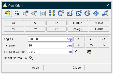
- Dynamic Viewing Options Toolbar: These options use mouse actions to dynamically orient the object in view. Mouse actions are different, depending on the active option-see the table below for details. Dynamic viewing options are also available on the Toolbar.


-
↘️ Shortcuts:
-
You can quickly fit, reverse, or orient the model in one of the defined views by right-clicking in the view and then selecting Fit, Reverse, or Select View from the menu that displays.
-
Use the thumb wheel on the mouse to Zoom to Box. Click on the thumb wheel and drag the mouse to define the box to zoom to. The zoom takes place when you release the thumb wheel.
-
Standard drawing view buttons

These buttons orient the object in the selected standard drawing view and automatically fits the object in the view. -
Rotation Options:
-
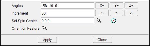
Angles — Absolute rotation about the view coordinate system X Y Z axes, respectively. The three values are separated by spaces.
-
Increment — Degrees of incremental rotation to apply when a rotation button is pressed (see below).
-
Rotation buttons (X+/X-, Y+/Y-, Z+/Z-) — axis and direction in which to apply incremental rotation specified by the Increment value.
-
Set Spin Center — Specify a point to be used as the center of rotation during dynamic rotations. Click in the Spin Center text field so that it becomes active, then either enter XYZ values (separated by spaces) in the field and click on the Apply button or click on a position on an object (not the background) in the view to specify the Spin Center point. The values are applied to the "active" view. If a workpiece view is the active view, the coordinates are relative to the origin of the workpiece coordinate system. If the "active" view is a machine view, the coordinates are relative to the origin of the machine coordinate system.
Press to display the Spin Center marker
  and activate the point for the active view. To de-activate Spin Center point, press the button again. You can specify a different rotation point for each view. When you close the View Orient window, the Spin Center markers will no longer be displayed but the activated Spin Centers will remain active. When you use one of the dynamic rotation features described above in a view with an active Spin Center, the Spin Center point will be used as the center of rotation instead of the view coordinate system origin.
↘️ Shortcut: You can quickly change the spin center location by right-clicking on the position on an object (not on the background) in the view where you want the spin center located, and then left-click on Spin Center in the menu that displays. The spin center will be located at your pick point. -
Orient On Feature — Resets the view to the normal of the feature selected in the graphics area. The modified view is centered on the position of the selection vector. Click on the Orient on Feature button
 so that it becomes activated. Click on a feature in the Graphics window.
 -
Apply — Use the Apply button to accept the current window settings and leave the View Orient window open for additional work.
-
Close — Use to close the View Orient window.
Zoom/Fit group — The buttons in this group enable you to zoom in or out and fit various tools to the maximum visible size in the graphical display.
Dynamic group — The buttons in this group are used rotate and pan the current view in the graphical display. There is also a dynamic zoom option which enables you to zoom in and out through the use of the mouse wheel rather than having to select the Zoom In and Zoom Out buttons respectively.
Display group — The buttons in this group are used to change the ways in which the materials in the graphical display are presented.
-
Shaded with — Use this pulldown to select between various draw mode options.
-
Shaded — Choose between shaded and flat background options.
-
Ambient Occlusion — When active, approximates how bright light should be shining on specific surface parts.
-
Spun Tool Display — When on, tools in the Tool Display Area will appear as they would when they are in use. This feature will remain active until it is toggled off (unchecked) or until you exit Optimizer. Spun Tool Display is off by default at the start of each Optimizer session.
Import tab

Convert group
CAD — Opens the Import CAD Tool window enabling you to read, extract, identify tool insert and holder solid models from a CAD system, and then import them into Optimizer's Tool Manager. Currently, only STEP and CATIA V5 files are supported.
DXF — Opens the DXF Geometry window enabling you to import two dimensional geometry from files which comply with a de facto CAD system standard, the Data eXchange Format (DXF).
Create from APT NC Program — Causes the Tool Manager to scan the NC program files for cutter statements (including CUTTER, PPRINT-Vericut TC, etc.), and create a tool library file named <user filename>.tls. The APT NC program tools replace the current tool library contents. Tools are numbered sequentially, beginning at 1.
Partners group
CoroPlus Tool — Displays the Import CoroPlus Tools window enabling you to access tool assembly models and application data from CoroPlus ToolLibrary software.
MachiningCloud Tool — Opens the Import MachiningCloud Tools window enabling you to import tools from the machining cloud to Tool Manager.
TDM — Displays the TDM Interface window enabling you to access tools from the TDM Systems', Tool Data Management (TDM) system database.
TDM Global Line — Displays the TDM Global Line Interface window enabling you to access this variant of the TDM Systems', Tool Data Management (TDM) system database.
ToolsUnited — Displays the TolsUnited window enabling you to use that interface for importing tools.
WinTool — Displays the (WinTool) WT-ToolExport dialog by launching the executable directly from the Optimizer Tool Manager Import ribbon. The WinTool button should be automatically active if WinTool software is installed and detected.
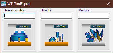
📝 NOTE: The WinTool software must be open to use the WT-ToolExport dialog.
ZOLLER Database — Displays the ZOLLER Database Access window enabling you to retrieve tool data from ZOLLER Database Service and import selected tools from a setup sheet in the ZOLLER database to the Optimizer Tool Manager.
Utilities tab
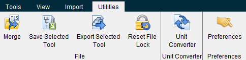
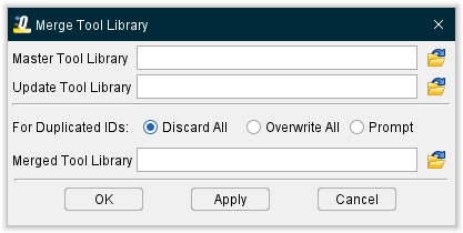
Merge — Opens the Merge Tool Library window enabling you to merge two tool libraries into one.
-
Master Tool Library — Enter the /path/filename, of the master tool library file, in the Master Tool Library text field or click on the
 (Browse) icon to display the Open file selection window and use it to specify /path/filename of the master tool library file.
 -
Update Tool Library — Enter the /path/filename, of the tool library file that will be merged into the master tool library file, in the Update Tool Library text field, or click on the
(Browse) icon to display the Open file selection window and use it to specify the /path/filename of update tool library file. -
For Duplicated IDs — Use to select one of the options to specify how duplicate tool IDs are to be handled during the merge operation.
-
Discard All — When toggled "On", duplicate tool IDs in the Update Tool Library will be discarded.
-
Overwrite All — When toggled "On", duplicate tool IDs in the Master Tool Library will be overwritten by the ones in the Update Tool Library.
-
Prompt — When toggled "On", a window will display when a duplicate tool ID is encountered, enabling you to specify whether to Discard the duplicate tool ID in the Update Tool Library, or Overwrite duplicate tool ID in the Master Tool Library, or to Quit the merge operation.
-
Merged Tool Library — Enter the /path/filename, for the merged tool library file, in the Merged Tool Library text field, or click on the
(Browse) icon to display the Save Tool Library As file selection window and use it to specify the /path/filename of the merged tool library file. -
OK — Starts the merge operation and closes the Merge Tool Library window.
-
Apply — Starts the merge operation and leaves the Merge Tool Library window open for additional merges.
-
Cancel — Closes the Merge Tool Library window without doing the merge operation.
Save Selected Tool — Use to save the selected tool to a specified tool library file. Selecting Save Selected Tool displays a file selection window enabling you to specify a /path/filename for the tool library file.
Export Selected Tool — Use to export the highlighted tool in the specified format (STL or VRML). Selecting Export Selected Tool displays a file selection window enabling you to specify a /path/filename for the file to receive the exported tool data.
Reset Lock File — Enables you to delete an existing Tool Library file lock. Selecting Tool Manager, File menu > Reset File Lock will display the following message where “QA” is the logon ID of the user that currently has the Tool Library file locked.
Unit Converter — This command button converts selected tools from inch to millimeter or from millimeter to inch measurements depending on what the current values in use are. It converts Stock Material Record, driven point and cutter comp values, any tool type and component type. Multi tool selection is also possible. When a user performs a tool unit change by clicking on the new button or by changing tool unit from the tool page, a new pop up message comes up, asking the user to convert values or keep them as is.
Preferences — Use this command button to open the Tool Manager Preferences window enabling you to control how information in the Tool Manager is displayed.