Tool Information tab
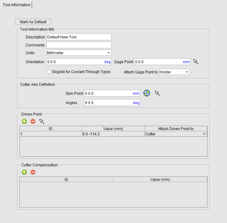
The Tool Information tab is displayed when a tool record in the Tool List Area is highlighted or whenever a new tool assembly is added.
 Mark as Default — Use to specify an existing tool as the default tool for that tool category. Default tools become the base tool whenever a new tool is added in the Tool Manager. Each tool category can have only one default tool at most.
Once Mark as Default is selected, the file ‘default_tools.prefs’ is added to the User preferences at the ‘%APPDATA%/Roaming/Vericut’ location. The file is updated whenever a new default is selected.
📝 NOTE: Marking a tool as a default cannot be undone. That selected tool remains as the default for that tool category until a new default is selected so care must be taken when selecting a default.
Imported elements of a tool (such as CAD, SOR, or Sweep) will not be carried over to the default tool preference file. Cutters and inserts are also not carried over meaning that cutters and inserts do not become the default tool components for their category. Holders are carried over unless “Do Not Add Holders” is toggled on (checked) in the ‘Preferences’ dialog of Tool Manager.
Comments — This field enables you to add comments related to the tool/tool assembly. The comment text is stored with the tool ID.
Units — Use to enter, and display, the unit measurement system (Inch or Millimeter) in which the tool is defined. If the tool units are different from the Optimizer session units when loaded, then tool description values are converted appropriately.
Orientation — Use to specify, and display, the orientation of the tool assembly when loaded for cutting. Three values are entered (separated by spaces) to define the X, Y, Z rotation angles, respectively. Angle values are in degrees, relative to the tool origin. Rotation occurs about the tool's gage point.
📝 NOTE: This feature is only applicable when NC Program Type is G-Code Data.
Eligible for Coolant Through Types — Use to define Tool eligibility to receive coolant through types during machining. During Optimizer simulation if one of CoolantAirThru or CoolantThru macros are enabled, Optimizer will generate an error message in case Eligible for Coolant Through Types box is not checked for the active tool. Eligible for Coolant Through Types feature is available for Mill, Hole-Making, Turning, Multi-Station, Thread Mills and Polisher tool type.
Attach Gage Point to — Use to associate the tool's Gage Point relative to the tool origin, or to a specific holder component in the tool assembly. When a holder with attached Gage Point is moved, the Gage Point also moves equally with the holder so it retains the same position relative to the holder.
Cutter Axis Definition
Use the features of this group to adjust the spin axis of angle head and driven type tools when the spin axis of the tool is not aligned the same Z axis of the Gage Point. This is particularly necessary when a tool assembly is built from holder to tip (per ISO 13399) instead of tip to holder.
Spin Point — Use to enter an X Y Z coordinate value to define the location of the spin point (typically at the tip of the tool or the Driven Point). This will display a CIP (Coordinate system In Process) coordinate system at the entered location once a value other than 0 0 0 is defined. You can also use the  (Use the driven point) icon to automatically align the Spin Point to the same location fo the first defined Driven Point. The Spin Point field will display greyed out and uneditable. If the Driven Point values changes the Spin Point will automatically update. Or use the
  (Pick the spin point) icon to define a location anywhere on the tool assembly for the Spin Point. Any surface vector of a tool assembly can be selected.
Angles — Use this feature to specify the absolute XYZ rotation of the Spin Point (CIP) coordinate system, separated by spaces.
📝 NOTE: It is helpful when defining the Spin Point of a tool assembly to display the tool spinning in Tool Manager (RMB in the Tool Manager View > Spun Tool Display)
Driven Point/Focal Point — Use to add one or more Driven Point records to the highlighted tool. Click on the  icon to add Driven Point records to the list. This option becomes Focal Point when used in conjunction with the Additive tool.
To remove a record from the list, select the record that is to be removed so that it becomes highlighted and then click on the  icon.
icon.
Optimizer assigns a default ID but you can modify it if you choose by double clicking on the current ID value so that it becomes highlighted and then edit the value as desired. Optimizer assigns a default Driven Point value of 0 0 0 but you can modify it by double clicking on the current value so that it becomes highlighted and then edit it as desired.
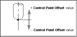
This feature is used to specify an offset for the tool control point, or "driven point". Material is removed based on motion commands and the tool shape relative to the control point. For milling tools, a positive value moves the control point in the positive tool axis direction (closer to the spindle), while a negative value moves the control point in the opposite direction.
📝 NOTE: Optimizer material removal for milling tools does not support driven points with X- or Y- offsets, only Z-offsets are allowed. If you wish to drive the machine with an X, or Y, offset driven point, and to have the correct material removal, you should define 2 driven points for the tool. For example, to drive the machine with an X offset, create the 1st driven point (0,0,0) and the 2nd (6,0,0).
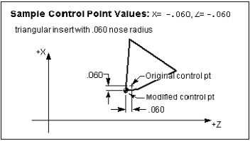
For turning tools, XYZ values (separated by spaces) are entered relative to the spindle axis (Z), and cross-slide axis (X).
Sample Driven Point values for a milling tool:
Sample Driven Point values for a turning tool:
When defined, the "Driven Point" view attribute displays as a hollow target symbol  at the control point location.
Attach Driven Point to — Use to associate the tool's Driven Point to a Cutter component so that if the cutter is moved in the tool assembly, the driven point stays connected in the proper relationship to the cutter. The “Tool Origin” option can be used to define a static driven point location.
Cutter Compensation — Use to add one or more Cutter Compensation records for the highlighted tool. Click on the icon to add Cutter Compensation records to the list.
To remove a record from the list, select the record that is to be removed so that it becomes highlighted and then click on the icon.
Optimizer assigns a default ID but you can modify it if you choose by double clicking on the current ID value so that it becomes highlighted and then edit the value as desired. To modify the current Cutter Compensation value, double clicking on the current value so that it becomes highlighted and then edit it as desired.