Turn Tool
A turning tool assembly consists of these components:
Holder —The Holder component grips the Cutter and holds it in the NC machine for cutting and is described using the Tool Component tab (Holder) features in Tool Manager.
The holder component is also used for collision detection. Optimizer enables using multiple holder components. Other non-cutting components found in Turning tool assemblies, such as: backup blocks, extensions, adapters, etc. are described using "Holder" components.
Cutter — Cutting portion of the tool, sometimes referred to as a turning "insert" is used to remove material.
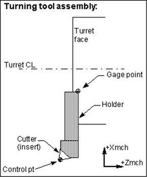
Turning tool control point
The tool control point, or "driven point" is a point relative to the tool assembly that the NC data is commanding to move. Material is removed based on motion commands and the tool shape, relative to the control point. By default, Otpimizer assumes the center the turning tool tip is being driven. However, this relationship can be changed by including a Driven Point record for the tool in the Tool Manager window, Tool Information tab.
In cases where a gage point is driven, such as with G-Code data for a machine expecting to drive the turret face or center, gage offset values are often used. These values establish where the NC data control point is, relative to the actual machine driven point. Optimizer realistically simulates this programming method by including a Gage Point location for the tool in the Tool Manager window, Tool Information tab.
Tool Component tab (Turn Insert)
Opened via adding or modifying a turning Insert Cutter tool component, this tab is used to describe the insert shape for the "Cutter" component in a turning tool assembly. Options are available to define the cutter insert via ISO standard shapes, profile sketcher, or reference a cutter insert in another tool assembly.
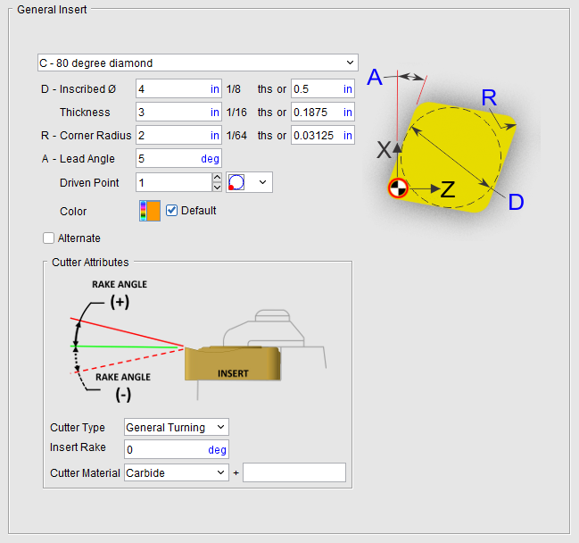
Component Type — Use to specify the type of component you are creating. In this case an Insert Cutter for a turning tool.
ID — Use to specify the ID for the component you are creating. If not specified, Optimizer will assign a unique default ID.
Tool shape icons — Selecting an icon configures the bottom half of the window to define the selected cutter shape.
Options:
 (General Insert) — Displays the General Insert features enabling you to define ISO standard insert shapes.
The parameters and diagram will vary depending on the Insert Type selected from the list. Only the parameters required to describe a particular insert type will be displayed. Select the desired insert type from the pull-down list.
| Insert Type | Parameter Description | |
|---|---|---|
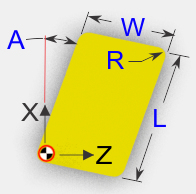
| A - 85 degree parallelogram | L - Length W - Width Thickness R - Corner Radius A - Lead Angle Driven Point Color Alternate |
 |
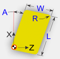
| B - 82 degree parallelogram | L - Length W - Width Thickness R - Corner Radius A - Lead Angle Driven Point Color Alternate |
 |
| C - 80 degree diamond | D – Inscribed Diameter (in) L – Length (mm) Thickness R - Corner Radius A - Lead Angle Driven Point Color Alternate |
Inch Millimeter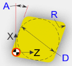 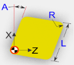 |
| C - 100 degree diamond | D – Inscribed Diameter (in) L – Length (mm) Thickness R - Corner Radius A - Lead Angle Driven Point Color Alternate |
Inch Millimeter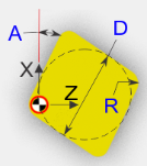 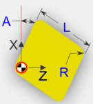 |
| D - 55 degree diamond | D – Inscribed Diameter (in) L – Length (mm) Thickness R - Corner Radius A - Lead Angle Driven Point Color Alternate |
Inch Millimeter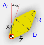 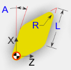 |
| E - 75 degree diamond | D – Inscribed Diameter (in) L - Length (mm) Thickness R - Corner Radius A - Lead Angle Driven Point Color Alternate |
Inch Millimeter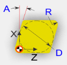 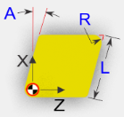 |
| H - Hexagon | D - Inscribed Diameter L – Length (mm) Thickness R - Corner Radius A - Lead Angle Driven Point Color Alternate |
Inch Millimeter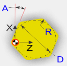 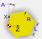 |
| K - 55 degree parallelogram | L - Length W - Width Thickness R - Corner Radius A - Lead Angle Driven Point Color Alternate |
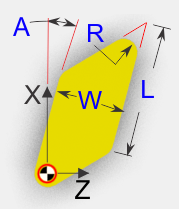 |
| L - Rectangle | L - Length W - Width Thickness R - Corner Radius A - Lead Angle Driven Point Color Alternate |
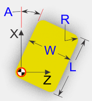 |
| M - 86 degree diamond | D – Inscribed Diameter (in) L – Length (mm) Thickness R - Corner Radius A - Lead Angle Driven Point Color Alternate |
Inch Millimeter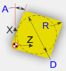 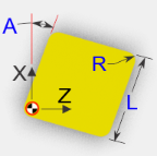 |
| O - Octagon | D – Inscribed Diameter (in) L – Length (mm) Thickness R - Corner Radius A - Lead Angle Driven Point Color Alternate |
Inch Millimeter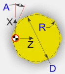 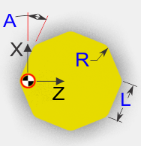 |
| P - Pentagon | D – Inscribed Diameter (in) L – Length (mm) Thickness R - Corner Radius A - Lead Angle Driven Point Color Alternate |
Inch Millimeter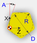 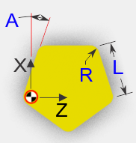 |
| R - Round | D – Inscribed Diameter Thickness Driven Point Color Alternate |
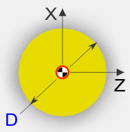 |
| S - Square | D – Inscribed Diameter (in) L – Length (mm) Thickness R - Corner Radius A - Lead Angle Driven Point Color Alternate |
Inch Millimeter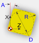 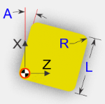 |
| T - Triangle | D – Inscribed Diameter (in) L – Length (mm) Thickness R - Corner Radius A - Lead Angle Driven Point Color Alternate |
Inch Millimeter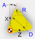 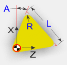 |
| V - 35 degree diamond | D – Inscribed Diameter (in) L – Length (mm) Thickness R - Corner Radius A - Lead Angle Driven Point Color Alternate |
Inch Millimeter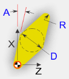 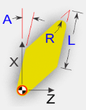 |
| W - 80 degree trigon | D – Inscribed Diameter (in) L – Length (mm) Thickness R - Corner Radius A - Lead Angle Driven Point Color Alternate |
Inch Millimeter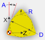 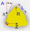 |
| Custom diamond | D – Inscribed Diameter (in) L – Length (mm) Thickness R - Corner Radius A - Lead Angle T - Tip Angle Driven Point Color Alternate |
Inch Millimeter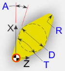 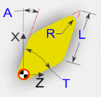 |
| Custom parallelogram | L - Length W - Width Thickness R - Corner Radius A - Lead Angle T – Tip angle Driven Point Color Alternate |
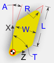 |
Driven Point — Use to specify the driven point for the insert. You can specify multiple driven points. Use the number box to specify which driven point that you are defining. In the picture below, driven point 2 is being defined. Select the desired driven point location for each driven point from the pull-down list. This feature is only available for Turn inserts.
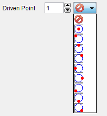
Color — Color that the tool component is to be displayed in Optimizer. Toggle on (check) the Default check box to have the Color feature automatically switch to the designated default color.
Alternate — When toggled "on" (checked) this feature designates the cutter that is being created as an "alternate" or "secondary" cutter for a particular tool assembly. This feature enables you to switch between a "primary" and "alternate" cutter shape, in order to support tools such as back-boring tools.
 (Groove Insert) — Displays the Groove Insert features enabling you to define ISO standard groove insert shapes.
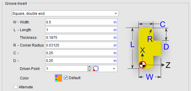
The parameters and diagram will vary depending on the Insert Type selected from the list. Only the parameters required to describe a particular insert type will be displayed. Groove Insert features are only available for defining Turning cutters.
| Insert Type | Parameter Description | |
|---|---|---|
| Square, double end | W - Width L - Length Thickness R - Corner Radius C D Driven Point Color Alternate |
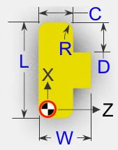 |
| Radius, double end | W - Width L - Length Thickness R - Corner Radius D Driven Point Color Alternate |
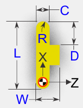 |
| 40 degree V, double end | W - Width L - Length Thickness R - Corner Radius C D Driven Point Color Alternate |
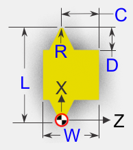 |
| 45 degree chamfer, double end | W - Width L - Length Thickness R - Corner Radius C D Driven Point Color Alternate |
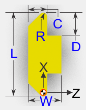 |
| Square, single end | W - Width L - Length Thickness R - Corner Radius C D Driven Point Color Alternate |
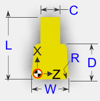 |
| Chamfer, single end | W - Width L - Length Thickness R - Corner Radius C D A - Chamfer Angle Driven Point Color Alternate |
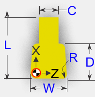 |
| Round, single end | L - Length Thickness R - Corner Radius C Driven Point Color Alternate |
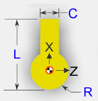 |
| Radius, single end | L - Length Thickness R - Corner Radius C B – Side Angle Driven Point Color Alternate |
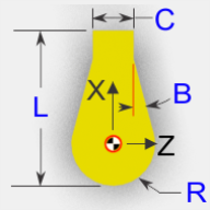 |
Driven Point — Use to specify the driven point for the insert. You can specify multiple driven points. Use the number box to specify which driven point that you are defining. In the picture below, driven point 2 is being defined. Select the desired driven point location for each driven point from the pull-down list. This feature is only available for Turn inserts.
Color — Color that the tool component is to be displayed in Optimizer. Toggle on (check) the Default check box to have the Color feature automatically switch to the designated default color.
Alternate — When toggled "on" (checked) this feature designates the cutter that is being created as an "alternate" or "secondary" cutter for a particular tool assembly. This feature enables you to switch between a "primary" and "alternate" cutter shape, in order to support tools such as back-boring tools.
 (Thread Insert ) — Displays the Thread Insert features enabling you to define ISO standard thread insert shapes.
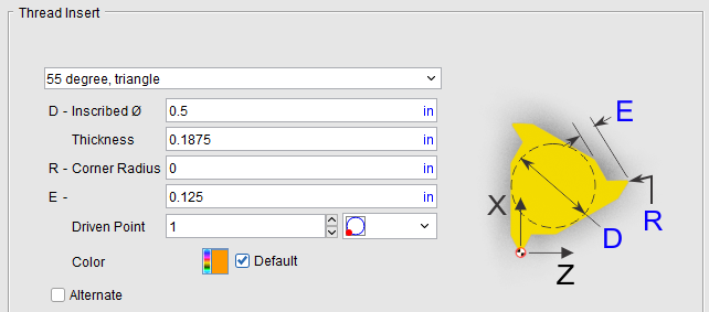
The parameters and diagram will vary depending on the Insert Type selected from the list. Only the parameters required to describe a particular insert type will be displayed. Thread Insert features is only available for defining turning cutters.
| Insert Type | Parameter Description | |
|---|---|---|
| 55 degree, triangle | D – Inscribed Diameter (in) L – Length (mm) Thickness R - Corner Radius E Driven Point Color Alternate |
Inch Millimeter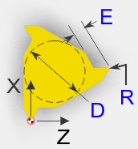 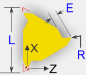 |
| 60 degree, triangle | D- Inscribed Diameter (in) L – Length (mm) Thickness R - Corner Radius E Driven Point Color Alternate |
Inch Millimeter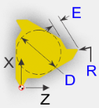 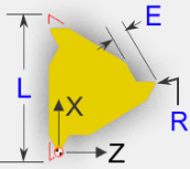 |
| 30 degree, trapeze triangle | D – Inscribed Diameter (in) L – Length (mm) Thickness R - Corner Radius E F – Flat Driven Point Color Alternate |
Inch Millimeter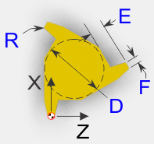 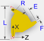 |
| ACME, triangle | D – Inscribed Diameter (in) L – Length (mm) Thickness R - Corner Radius E F – Flat Driven Point Color Alternate |
Inch Millimeter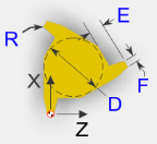 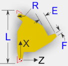 |
| Buttress, triangle, right hand | D – Inscribed Diameter (in) L – Length (mm) Thickness R - Corner Radius E F – Flat Driven Point Color Alternate |
Inch Millimeter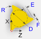 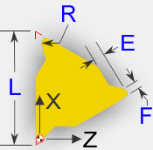 |
| Buttress, triangle, left hand | D – Inscribed Diameter (in) L – Length (mm) Thickness R - Corner Radius E F – Flat Driven Point Color Alternate |
Inch Millimeter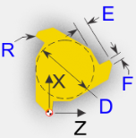 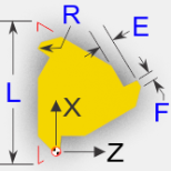 |
| 60 degree, double end, asymmetric | W - Width L - Length Thickness R - Corner Radius E Driven Point Color Alternate |
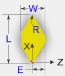 |
| 60 degree, double end, symmetric | W - Width L - Length Thickness R - Corner Radius E Driven Point Color Alternate |
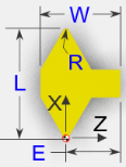 |
| ACME, double end | W - Width L - Length Thickness R - Corner Radius E F – Flat Driven Point Color Alternate |
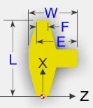 |
| Buttress, double end | W - Width L - Length Thickness R - Corner Radius E F – Flat Driven Point Color Alternate |
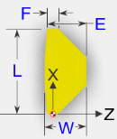 |
Driven Point — Use to specify the driven point for the insert. You can specify multiple driven points. Use the number box to specify which driven point that you are defining. In the picture below, driven point 2 is being defined. Select the desired driven point location for each driven point from the pull-down list. This feature is only available for Turn inserts.
Color — Color that the tool component is to be displayed in Optimizer. Toggle on (check) the Default check box to have the Color feature automatically switch to the designated default color.
Alternate — When toggled "on" (checked) this feature designates the cutter that is being created as an "alternate" or "secondary" cutter for a particular tool assembly. This feature enables you to switch between a "primary" and "alternate" cutter shape, in order to support tools such as back-boring tools.
 (Sweep Profile) — Opens the Profile Sketcher window in “sweep solid” mode enabling you to create Cutter components by defining a profile to be swept a specific distance to create the cutter insert.
 (Reference) — Displays the Reference Features enabling you to "reference" a tool component in another tool library file for use in the current tool library file.
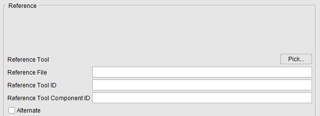
Pick — Pressing the Pick button displays the Search Tool window enabling you to search existing tool libraries for tools with specific attributes that you want to "reference".
Reference File — Enter the /path/filename of the tool library file containing the tool component to be referenced in the text field or use the Pick button to display the Search Tool window and use it to select the tool library file.
Reference Tool ID — Enter tool ID of the tool component to be referenced in the text field or use the Pick button to display the Tool Search window and use it to select the tool component to be referenced. In the sample tool record in the picture below, the Reference Tool ID is 6
Reference Tool Component ID — Enter tool component ID of the tool component to be referenced in the text field or use the Pick button to display the Tool Search window and use it to select the tool component to be referenced. In the sample tool record in the picture below, the Reference Tool Component ID is Cutter1

Alternate — When toggled "on" (checked) this feature designates the cutter that is being created as an "alternate" or "secondary" cutter for a particular tool assembly. This feature enables you to switch between a "primary" and "alternate" cutter shape, in order to support tools such as back-boring tools.
 (Model File) — The Model File Features enable you to use an existing model or create a new Sweep Solid or Solid of Revolution using the Profile Sketcher to define a tool component.
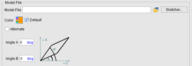
Model File — Enter the /path/filename of the model file or click on the  (Browse) icon to display the Open file selection window and use it to specify the /path/filename of the model file.
Sketcher — Displays the Profile Sketcher window enabling you to edit or create a "swept solid (.swp)" or "solid of revolution (.sor)" model file. This feature is only available the selected file is a SOR or SWEEP file type. To create a new SOR or SWEEP model file, clear the Model File text field and press Sketcher.
Color — The Color icon, enables you to specify a color for that particular tool. The color of the Color icon shows the current color of the tool. To change the color, click on the  (Color Palette) icon to display the color palette window shown below.
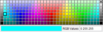
Click on a color in the color palette window, to specify the color for the tool. The color palette window will close and the right side of the  (Color Palette) icon in the Color window will update to reflect the selected color.
To close the color palette window without changing the color, click on the  in the upper right corner of the color palette window.
Alternate — When toggled "on" (checked) this feature designates the cutter that is being created as an "alternate" or "secondary" cutter for a particular tool assembly. This feature enables you to switch between a "primary" and "alternate" cutter shape, in order to support tools such as back-boring tools.
Angle A and Angle B — The angle corresponds to the non-rotated tool (as seen from Tool Man) with +Z to your right, and +X up. Zero degrees is along the +Z, and positive angle is CCW. The angle can be specified as a positive or negative angle.
Cutter Attributes
Cutter Type — Use to select the type of cutter you want. Options are General Turning and Parting Groove.
Insert Rake — Sets the degree for Force optimization.
Cutter Material — Selects the material the cutter is made of and enables you to set the tolerance levels.