Holders
Holders are created whenever a new tool is added. The Holder window is used to describe the shape of a selected "Holder" component in a tool assembly. Options are available to define the holder via parametric shapes, profile sketcher, or reference a holder in another tool assembly. More than one holder can be used in a tool assembly. An error similar to "HOLDER removed material..." is reported when the non-cutting portion of the cutter removes material. Material removed is shaded using the red Error color.
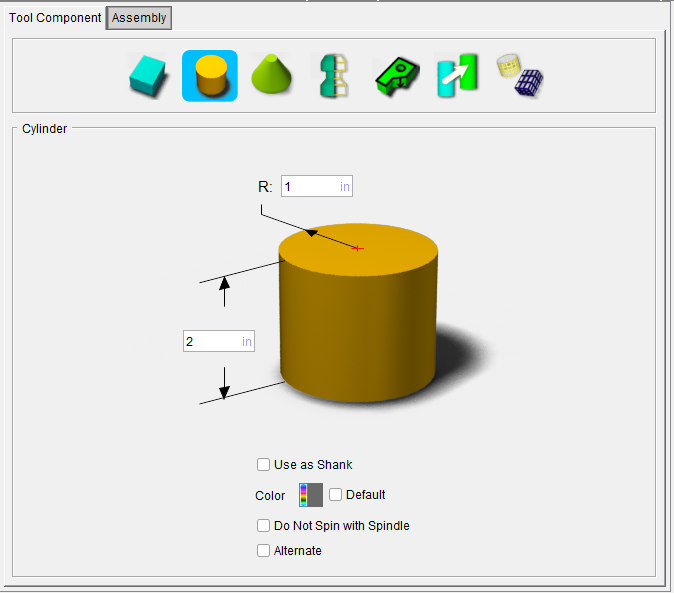
Holder icons — Selecting an icon configures the bottom half of the window with the parameters required to define the holder shape.
Options:
 (Block) — Opens the Block feature definition panel enabling you to specify a block as a holder and specify the holders’ other characteristics.
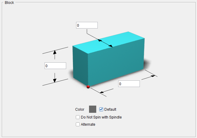
💡 Tip: Hold the cursor over a number field in the tool diagram to see a tip indicating what value the field represents.
Length (L) — Use to specify the length of the block.
Width (W) — Use to specify the width of the block
Height — Use to specify the height of the holder component.
Color — Color that the tool component is to be displayed in Optimizer
Do Not Spin with Spindle — When toggled "on" (checked), indicates that the holder component does not spin.
Alternate — When toggled "on" (checked) this feature designates the holder that is being created as an "alternate" or "secondary" holder for a particular tool assembly. This feature enables you to switch between a "primary" and "alternate" holder shapes.
The AlternateTool macro is used to specify whether to use the "primary" (Override Value = 0) holder shape or to use the "alternate" (Override Value = 1) holder shape.
 (Cylinder) — Opens the Cylinder feature definition panel enabling you to specify a cylinder as a holder and specify the holders’ other characteristics.
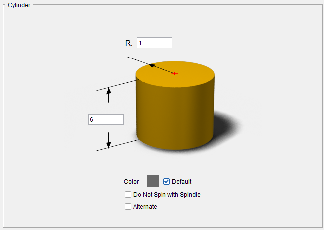
💡 Tip: Hold the cursor over a number field in the tool diagram to see a tip indicating what value the field represents.
Radius (R) — Use to specify the radius of the cylinder.
Height — Use to specify the height of the holder component.
Color — Color that the tool component is to be displayed in Optimizer.
Do Not Spin with Spindle — When toggled "on" (checked), indicates that the holder component does not spin.
Alternate — When toggled "on" (checked) this feature designates the holder that is being created as an "alternate" or "secondary" holder for a particular tool assembly. This feature enables you to switch between a "primary" and "alternate" holder shapes.
The AlternateTool macro is used to specify whether to use the "primary" (Override Value = 0) holder shape or to use the "alternate" (Override Value = 1) holder shape.
 (Cone ) — Opens the Cone feature definition panel enabling you to specify a cone as a holder and specify the holders’ other characteristics.
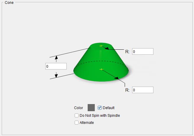
💡 Tip: Hold the cursor over a number field in the tool diagram to see a tip indicating what value the field represents.
Height — Use to specify the height of the holder component.
Top Radius (R2) — Use to specify the radius at the top of the cone.
Bottom Radius (R1) — Use to specify the Radius at the bottom of the cone.
Color — Color that the tool component is to be displayed in Optimizer.
Do Not Spin with Spindle — When toggled "on" (checked), indicates that the holder component does not spin.
Alternate — When toggled "on" (checked) this feature designates the holder that is being created as an "alternate" or "secondary" holder for a particular tool assembly. This feature enables you to switch between a "primary" and "alternate" holder shape.
The AlternateTool macro is used to specify whether to use the "primary" (Override Value = 0) holder shape or to use the "alternate" (Override Value = 1) holder shape.
 (Revolve Profile) — Opens the Profile Sketcher window in “solid of revolution” mode enabling you to create Revolved Cutter components by rotating a defined profile around the Z- axis.
 (Sweep Profile) — Opens the Profile Sketcher window in “sweep solid” mode enabling you to create Cutter components by defining a profile to be swept a specific distance to create the cutter insert.
 (Reference) — Displays the Reference Features enabling you to "reference" a tool component in another tool library file for use in the current tool library file.
The Reference Features enable you to "reference" a tool component in another tool library file for use in the current tool library file.
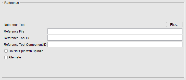
Reference features:
Pick — Pressing the Pick button displays the Search Tool window enabling you to search existing tool libraries for tools with specific attributes that you want to "reference".
Reference File — Enter the /path/filename of the tool library file containing the tool component to be referenced in the text field or use the Pick button to display the Search Tool window and use it to select the tool library file.
Reference Tool ID — Enter tool ID of the tool component to be referenced in the text field or use the Pick button to display the Tool Search window and use it to select the tool component to be referenced. In the sample tool record in the picture below, the Reference Tool ID is 6
Reference Tool Component ID — Enter tool component ID of the tool component to be referenced in the text field or use the Pick button to display the Tool Search window and use it to select the tool component to be referenced. In the sample tool record in the picture below, the Reference Tool Component ID is Cutter1

Do Not Spin with Spindle — When toggled "on" (checked), indicates that the holder component does not spin.
Alternate — When toggled "on" (checked) this feature designates the cutter that is being created as an "alternate" or "secondary" cutter for a particular tool assembly. This feature enables you to switch between a "primary" and "alternate" cutter shape, in order to support tools such as back-boring tools.
The AlternateTool macro is used to specify whether to use the "primary" (Override Value = 0) cutter shape or to use the "alternate" (Override Value = 1) cutter shape.
 (Model File) — The Model File Features enable you to use an existing model or create a new Sweep Solid or Solid of Revolution using the Profile Sketcher to define a tool component.
The Model File features enable you to use an existing model or create a new Sweep Solid or Solid of Revolution using the Profile Sketcher to define a tool component. The features that display will vary depending on the type of tool component. Each of the variations is illustrated in the pictures below.
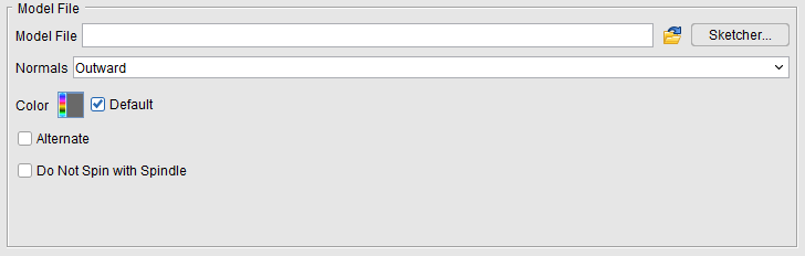
Model File — Enter the /path/filename of the model file or click on the ; (Browse) icon to display the Open file selection window and use it to specify the /path/filename of the model file.
Sketcher — Displays the Profile Sketcher window enabling you to edit or create a "swept solid (.swp)" or "solid of revolution (.sor)" model file. This feature is only available the selected file is a SOR or SWEEP file type. To create a new SOR or SWEEP model file, clear the Model File text field and press Sketcher.
Normals — Select the normal direction from the pull-down list. Choose Outward or Inward. This feature is only available for Holder components.
Color — The Color icon, enables you to specify a color for that particular tool. The color of the Color icon shows the current color of the tool. To change the color, click on the  (Color Palette) icon to display the color palette window shown below.
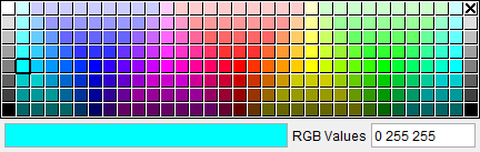
Click on a color in the color palette window, to specify the color for the tool. The color palette window will close and the right side of the  (Color Palette) icon in the Color window will update to reflect the selected color.
To close the color palette window without changing the color, click on the  in the upper right corner of the color palette window.
Alternate — When toggled "on" (checked) this feature designates the cutter that is being created as an "alternate" or "secondary" cutter for a particular tool assembly. This feature enables you to switch between a "primary" and "alternate" cutter shape, in order to support tools such as back-boring tools.
The AlternateTool macro is used to specify whether to use the "primary" (Override Value = 0) cutter shape or to use the "alternate" (Override Value = 1) cutter shape.
Do Not Spin with Spindle — When toggled "on" (checked), indicates that the holder component does not spin.