Assembly tab
The features on this tab are used translate or rotate a component in a tool assembly, or to move the selected component by assembling (mating or aligning) it with other objects in the tool assembly.
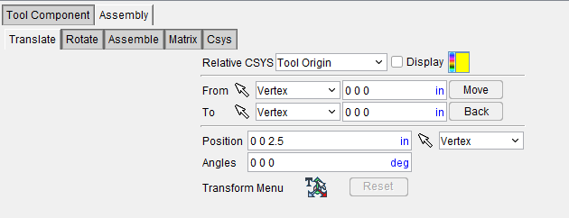
Common Features
Relative CSYS
Relative CSYS — Use this pulldown menu to select which CSYS to use. Options include Local, Parent, Machine Origin, Active CSYS, and Program_zero. You can toggle on (check) the adjoining Display checkbox to have the CSYS appear in the Graphics Area. The Color Palette icon  next to that checkbox can be used to change the color of the displayed CSYS.
Transform Menu
The Transform Menu appears at the bottom of every Assembly tab panel. The features here are used to control the positioning and moving of various elements.
Position — Specifies the absolute XYZ position of the tool component relative to the tool origin. Values in this field are separated by spaces. You can use the mouse icon and the pull down menu from which you can designate which feature to analyze in order to select a position from the Graphics Display Area by clicking on the desired location.
Angles — Specifies the absolute XYZ rotation of the tool component relative to the tool origin. Values in this field are separated by spaces.
Transform menu — Use the  icon to open the Transform Menu window, enabling you to create a transform menu.
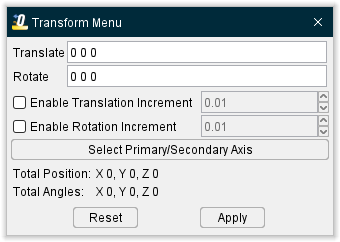
Once the Transform Menu window is open, a new kind of CSYS will appear in the Graphics Area. This axis can be used to manually manipulate the CSYS from the Graphics Area.
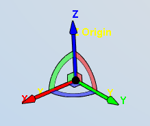
The axis arrows translate the object along the selected axis. A guideline will appear showing you the axis that will be traveled.
The outer rings rotate the object around the central axis. A rotational circle will appear showing you how the object will rotate.
The inner planes translate the object along two adjacent axes. Two guidelines will appear showing you the axes that will be traveled.
The origin snaps the object to the center points, edges, and corners of other objects in the scene.
Translate — Use this field to manually enter the XYZ units you want the CSYS to move by.
Rotate — Use this field to manually enter the XYZ degrees you want the CSYS to rotate by.
Enable Translation Increment — Toggle this feature on (checked) to specify positional movements down to the decimal point. The adjoining dropdown menu will then become active and you can manually enter the number of decimal points or use the arrow bars to increase or decrease the numbers by 0.1.
Enable Rotation Increment — Toggle this feature on (checked) to specify degree rotations down to the decimal point. The adjoining dropdown menu will then become active and you can manually enter the number of decimal points or use the arrow bars to increase or decrease the numbers by 0.1.
Select Primary/Secondary Axis — This button opens the Transform Menu supplemental window enabling you to
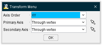
Axis Order — Allows you to specify which axes to give priority. Options include XY, YZ, and ZX.
Primary Axis and Secondary Axis — These enable you to select the vector where the axes will begin from. Use the dropdown menu to select the feature that will form the basis for the axis and then click the mouse pick icon  . Once the mouse pick icon is active, you can then click where you choose on the model in the Graphics Area to set the CSYS to that feature.
OK — Saves your selections and closes the window, returning you to the main Transform Menu window.
Reset — Undoes any changes made and closes the window.
Apply — Saves the changes made.
Reset — Undoes any changes made in the Transform Menu.
Translate tab
Translate tab features:
From / To — Use to move the tool component by specify the From and To locations, relative to the tool origin. XYZ values can be entered (separated by spaces), or selected by clicking in the field then clicking on a tool component shape. As you move the mouse over the tool, a crosshair and vector show you the pending pick-point location.
Move — Moves the selected object by the incremental distance, as calculated from the "From" point to the "To" point location.
Back — Moves the selected object by the incremental distance, as calculated from the "To" point to the "From" point location.
Rotate tab
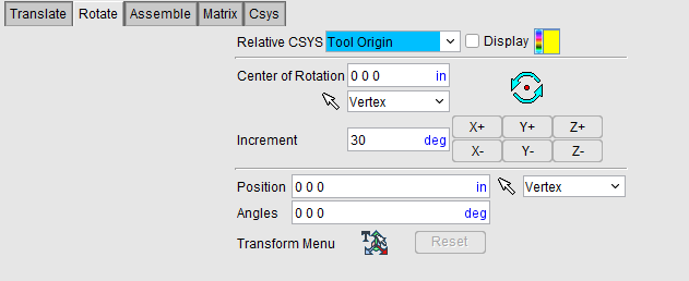
Rotate tab features:
Center of Rotation — Specifies XYZ point location about which to rotate the tool component. XYZ values can be entered in the Center of Rotation text field (separated by spaces), or selected by clicking in the Center of Rotation text field, then clicking on a tool component in the Tool Display area. To see the center of rotation, press  . To remove the center of rotation symbol press the button again, or close the window.
Increment — Specifies incremental degrees of rotation to apply when one of the rotation direction buttons are pressed.
Rotation buttons (X+/X-, Y+/Y-, Z+/Z-) — Use to apply the incremental degrees of rotation specified in the Increment field about the selected axis. Rotation occurs about the Center of Rotation relative to the tool origin.
Assemble tab
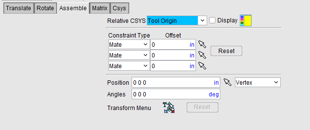
Follow these general steps to define a constraint for assembly:
- Choose the constraint type.
- Select a surface on the object to move.
- Select the surface to move the object relative to.
Assemble tab features:
Constraint Type — Specifies how to constrain selected surfaces during tool component movement. After selecting two surfaces to define a constraint, Optimizer moves the tool component and highlights the satisfied constraint with a checkmark.
Options:
Mate — Moves the tool component so the selected surface opposes the surface selected on the second tool component (surface normals oppose each other).
Align — Moves the tool component so the selected surface is aligned with the surface selected on the second tool component (surface normals point in the same direction).
Offset — Distance and direction in which to offset constrained surfaces, applied normal to the surface.
Reset — Resets constraints to receive new data.
Matrix tab
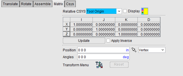
Matrix tab features:
Matrix table — The transformation matrix table is similar to the matrix used in programming APT tool paths. Its twelve parameters reveal the geometric attributes of the local (transformed) coordinate system (CSYS) in terms of the machine origin.
The format of the matrix table is as follows:
| I | J | K | D | |
|---|---|---|---|---|
| X | I1 | J1 | K1 | D1 |
| Y | I2 | J2 | K2 | D2 |
| Z | I3 | J3 | K3 | D3 |
Each row represents an axis of the local CSYS. The first three columns represent the vector associated with each axis: I1, J1, K1 as the positive X-axis vector; I2, J2, K2 as the positive Y-axis vector; and I3, J3, K3 as the positive Z-axis vector. The fourth column values D1, D2, D3 represent the coordinates of the origin point of the local CSYS.
📝 NOTE: If you prefer to see the Matrix Table displayed with the I, J, K along the vertical axis and the X, Y, Z along the horizontal axis, set the environment variable, CGTECH_MATRIX_FORMAT=VERTICAL.
Update — Updates the tool component location to reflect the matrix table transformation.
Apply Inverse On Update — When selected, inverts the matrix so that its twelve parameters reveal the geometrical attributes of the machine origin in terms of the local (transformed) coordinate system.
Csys tab
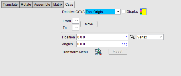
Csys tab features:
From — Use to specify the coordinate system to move the tool "from". Select the appropriate Csys from the pull-down list. The list contains all of the coordinate systems defined in the Coordinate Systems area of the Tool Manager.
To — Use to specify the coordinate system to move the tool "to". Select the appropriate Csys from the pull-down list. The list contains all of the coordinate systems defined in the Coordinate Systems area of the Tool Manager.
Move — Use to move the selected tool from the "From" Csys to the "To" Csys orientation.