Project Tree
Introduction to the Project Tree
The features on the Project Tree provide the tools required for the day to day use of Optimizer for setting up jobs for verification and simulation. The following basic concepts are needed to understand the process of setting up a job for Optimizer.
Project — A project consists of one or more setups (see Setup below) enabling you to simulate multiple operations in a single Optimizer session. Multiple Setups within a project can use the same, or different, machines.
Setup — A Setup is a collection of Optimizer settings and files (machine, control, tool library, etc.), NC program files, and Setup models (Stock, Fixture, Design) that define the machine operation to be simulated.
Current Setup — The Setup menu choices such as CNC Machine, NC Programs, etc., apply only to the Current Setup. A setup can be designated "current" either by selecting it using the Current Setup option in the Project menu, or by selecting it in the Project Tree. The "current" setup is indicated by a checkmark in the Current Setup menu and is displayed as bold in the Project Tree.
Active / Inactive Setup — A Setup can be designated as being in either an Active, or Inactive state. When a Setup is designated as Inactive, it is not simulated, as if it were not present in the overall process. An Inactive setup can however be designated as the "current" setup and modified. Inactive Setups are indicated by red text in both the Current Setup menu and in the Project Tree.
Project Tree Sidebar
The Project Tree Sidebar enables you to quickly move to a particular setup, or “branch” in the “current setup. Each of the icons is defined in more detail below. Holding the cursor over any of the icons displays a tip showing the “branch” that the icon will go to.

 (Setup) — Click in the Setup icon to display a pull-down list of setups available in the current project file. Select the desired setup from the list and the selected setup branch becomes highlighted and the setup becomes the “current” setup.
 (Control) — Click on the Control icon and the Control branch in the “current” setup becomes highlighted. Double-click on the Control icon to open a file selection window to load a control file.
 (Machine) — Click on the Machine icon and the Machine branch in the “current” setup becomes highlighted. Double-click on the Machine icon to open a file selection window to load a Machine file.
 (Coordinate Systems) — Click on the Coordinate Systems icon and the Coordinate Systems branch in the “current” setup becomes highlighted. Double-click on the Coordinate Systems icon to highlight Coordinate Systems branch in the “current” setup and expands the Coordinate Systems branch so that all of the Coordinate Systems in the branch are shown.
 (G-Code Offsets) — Click on the G-Code Offsets icon and the G-Code Offsets branch in the “current” setup becomes highlighted. Double-click on the G-Code Offsets icon to highlight G-Code Offsets branch in the “current” setup and expands the G-Code Offsets branch so that all of the G-Code Offset records in the branch are shown.
 (Tooling) — Click on the Tooling icon and the Tooling branch in the “current” setup becomes highlighted. Double-click on the Tooling icon to open the Tool Manager window enabling you to create and maintain Tool Library files containing descriptions of cutting tools, or tool assemblies.
 (NC Programs) — Click on the NC Programs icon and the NC Programs branch in the “current” setup becomes highlighted. Double-click on the NC Programs icon to open a file selection window enabling you to add one or more NC program files.
 (NC Subroutines) — Click on the NC Subroutines icon and the NC Subroutines branch in the “current” setup becomes highlighted. Double-click on the NC Programs icon to open a file selection window enabling you to add one or more NC subroutine files.
Configure Menus
Configure Project
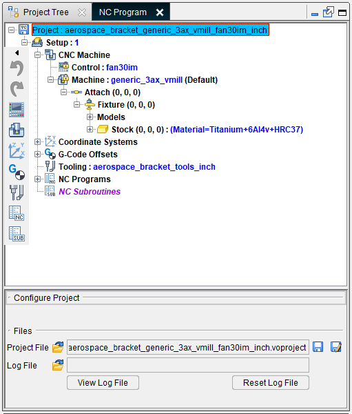
Project File — Use the Project File features to open and save project files.
 (Open File) — Opens a file selection window for you to select the Project File you wish to use for this program.
 (Save File) — Saves the existing file with any changes you may have made.
 (Save As File) — Opens a Save Project As window enabling you to save your file under any name you choose to enter.
Log File — Use the Log File features to save, view and clear log files (ref. Log File in the Getting Started section of Vericut Help).
(Open File) — Opens a file selection window enabling you to save the Log file.
Configure Setup
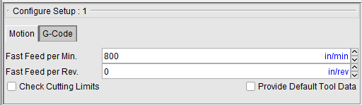
Motion tab
Fast Feed per Min. — The maximum Feedrate which material should be removed (or added). Motions that remove (or add) material with feedrates exceeding this value are considered potentially unsafe because they could cause tool breakage, machine malfunction, part damage, or incorrect additive bead. Material removed (or added) under excessive feedrate conditions is shaded in the Error color (typically red) and causes a "Fast feed rate" error.
Fast Feed per Rev. — When in FPR mode and the Fast Feed (FPR) value is non-zero, the fast feed rate will be checked against the Fast Feed (FPR) value. Otherwise: The fast feed rate will be checked against the Fast Feed (FPM) value.
For Tapping and Threading, the fast feed will be checked against the Fast Feed (FPM) value. To apply multiple FPR fast feed values, set Vericut-MODAL FASTFPR = “X.X,” where “X.X” is the value you need to set.
📝 NOTES:
-
Tapping and Threading (although in FPR mode), will not use the FPR value because this setting is typically much higher than normal FPR settings.
-
The default for the Fast Feed (FPR) is zero. If zero, it will not be used allowing existing jobs to continue running.
- You can use the Vericut MODAL Record to set Fast Feed values.
Check Cutting Limits — Toggle “on” (checked) to have Optimizer do the cutting limit checks during simulation. Cutting limit values are set in the Optimize Control window.
📝 NOTE: Turning on the Check Cutting Limits option internally turns on optimization logic. Running optimization in the background leads to a certain performance slow-down. Typically, with No Animation and without any collision checking and other costly options, the slow-down is in the range of 15-30%.
Optimization enables Optimizer to calculate more “true” values for the Tool Cutting Time and Tool Cutting Distance. Specifically, if a tool's motion starts in the air and then goes into the material, only the portion of the time/distance tool spends in the material will be added to these values. The accuracy of calculating the “in-material” values is mostly determined by the Resolution setting on the Optimize Control window.
Provide Default Tool Data — When this option is toggled on (checked), the Optimize Control window provides a host of tool information. Default Tool Data (DTDs) seen in Tool Manager consider the current Stock Material, the Cutter’s teeth count and Force settings, and the Cutting Limits Source for cutting data. For tools imported with cutting data, DTD reflects imported cutting data values. For tools that do not have imported cutting data, Optimizer attempts to retrieve cutting data from Tool Data for the current Stock Material. If cutting data isn’t found via either of those methods, then standard default SMR values are provided. In short, DTD data values are the same as a user gets when a new SMR is added to the Cutter.
G-Code tab
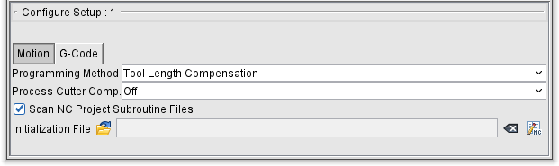
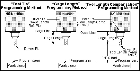
Programming Method — Describes the relationship between cutting tools and what is being driven by tool path file motion commands. (Take care NOT to describe the relationship between cutting tools and the driven point controlled by a CAM system.)
Options:
Tool Tip — XYZ values represent tool tip positions (center of the tool tip) at all times.
📝 NOTE: Tool length compensation codes (G43ZnHn/G49) do not appear in tool tip programmed tool paths. If these codes are present, use the Tool Length Compensation programming method.
Gage Length — XYZ values represent gage point positions. The gage point is typically the spindle face, where the centerline of the tool intersects the machine gage line. Gage length values must be supplied using Gage Offset in Tool Manager, or via entries in a Gage Offset table.
Tool Length Compensation — With comp. active (e.g. G43ZnHn) XYZ values represent tool tip positions relative to program zero. With comp. cancelled XYZ values represent machine gage point positions relative to machine zero. Use an Input Program Zero table to describe where the part zero is. Optimizer automatically calculates "H" offset values, or enters values in a Tool Length Compensation table. For proper tool loading on a 3-D machine supply gage offset values as described above for Gage Length programming method.
Process Cutter Comp. — This field determines whether or not we turn on Cutter Compensation “CDC” when specified in a program (for example: G41, G42). In addition, this field determines how we should default the “Cutter Comp Value” if it is not specified.
The “Cutter Comp Value” is the amount to adjust the toolpath (to the right or left) when CDC is active. For example: The program specifies to use Cutter Comp ID 4. We will look for this ID in the Cutter Compensation table for the current Tool (See Tool Manager). If it doesn’t exist, we can then either default the Cutter Comp Value to zero or to the full radius of the Tool.
📝 NOTE: The Cutter Comp Value is shown in the Status window in the “Others” section.
Options:
-
Off — Do not turn on CDC when specified and default the Cutter Comp Value to zero if ID is not found.
-
On – Default to Zero — Turn on CDC when specified, and default Cutter Comp Value to zero if ID is not found
-
On – Default to Full Radius — Turn on CDC when specified, and default the Cutter Comp Value to full radius if not found
📝 NOTE: The On/Off feature only applies to CDC. It does not apply to the compensation that occurs with Milling Pocket Cycles.
📝 NOTE: The resulting Cutter Comp Value is used by both CDC and Milling Pocket Cycles. See also the macro: CycleMillPocketToolRadiusLogic.
This GUI option can be overridden with the ProcessCutterComp macro.
The ProcessCutterComp macro will be disabled if “Disable ProcessCutterComp” is turned on within the G-Code Outputs window.
Scan NC Project Subroutine Files — When toggled “On” (checked), Optimizer will scan NC Project Subroutine Files. This is the default in order to maintain compatibility with existing jobs. When toggled "Off" (not checked), Optimizer will not scan NC Project Subroutine Files.
📝 NOTES:
-
Optimizer will still scan the machine and control subroutine files.
-
It is only valid to toggle this field Off when the file contains no branching (IF, DO, FOR, WHILE, GOTO, ...) and the name of the subroutine is the same as the name of the file.
Initialization File — Use this feature to specify the Setup Initialization File to be used. A Setup Initialization File is a text, or subroutine, file used to initialize variables used in the setup. The Setup Initialization File is processed at the same time as the "Start of Processing" event. Click on the (Add Setup Initialization File) icon to display the Setup Initialization Files file selection window and use it to specify the *path*filename of the Setup Initialization File to be used.
Use the  (Clear Setup Initialization File) to clear the Initialization File text field.
Use the  (Edit Setup Initialization File) to open the specified Setup Initialization File in a text editor window to enable viewing and/or modifying it.
Configure CNC Machine
📝 NOTE: Optimizer will come with a configured machine & Control setup by CGTech Tech Engineer.
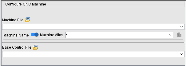
Machine File — Use the Machine File features to open and save machine files which contain data that describes NC machine construction, kinematics, and other properties.
 (Open Machine) — Displays the Open Machine window enabling you to open machine (.mch, .xmch) files.
Machine File Pull-down List — Click on the arrow button  at the end of the Machine File text field to display a list of all of the Machine files contained in the /library/ folder of your installation and select the desired machine file from the list.
Machine Name|Machine Alias toggle — Switch between using the default file name for your machine (Machine Name) or a nickname you can enter for yourself in the text field to the right of the toggle (Machine Alias).
 (Change Machine) — When the above toggle is set to Machine Name, this icon becomes active. Clicking it will open the Machine Settings window enabling you to edit which machine is active in the Project Tree.
Base Control File — Use the Base Control File features to open and save control files which contain data that describes how the NC control processes machine code data.
 (Open Control) — Displays the Open Control window enabling you to open control (.ctl, .xctl) files.
Control File Pull-down List — Click on the arrow button at the end of the Control text field to display a list of all the Control files contained in the "library" folder of your Optimizer installation and select the desired Control file from the list.
Configure Control
📝 NOTE: Optimizer will come with a configured machine & Control setup by CGTech Tech Engineer.
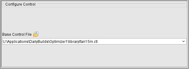
The features in this menu are the same as the features in the Base Control section of the CNC Machine menu above.
Configure Machine
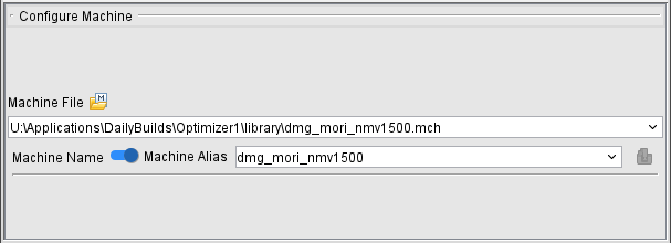
The features in this menu are the same as the features in the Machine File section of the CNC Machine menu above.
Configure Fixture
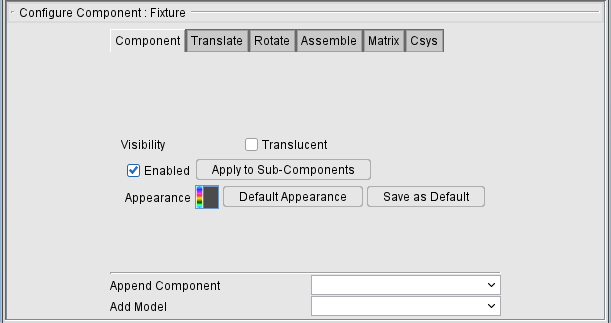
The Common Features of the Configure Fixture menu appear on every tab.
Append Component — The items displayed in the Append Component pull-down list will differ depending on the component type currently selected (highlighted) in the Project Tree.
Design — The Design component represents a solid or surface representation of the theoretical designed part.
Design Point — The Design Point component represents a point representation of the theoretical designed part.
Add Model — The Add Model pull-down list contains the model types that can be added to a component. Click on the arrow button  and select from the following model types:
Block — Selecting Block adds a default block model to the Project Tree and displays the Configure Model menu with Type set to "Block" enabling you to define the block's attributes and position.
Cone — Selecting Cone adds a default cone model to the Project Tree and displays the Configure Model menu with Type set to "Cone” enabling you to define the cone's attributes and position.
Cylinder — Selecting Cylinder adds a default cylinder model to the Project Tree and displays the Configure Model menu with Type set to "Cylinder" enabling you to define the cylinder’s attributes and position.
Model File — Selecting Model File displays the Open file selection window enabling you to specify the model file to add to the Project Tree. Once the model file is added to the Project Tree the Configure Model menu displays with Type set to "Model File" model's position.
Create Revolve — Selecting Create Revolve opens the Profile Sketcher window in "solid of revolution" mode.
Create Sweep — Selecting Create Sweep opens the Profile Sketcher window in "sweep solid" mode.
Create Sweep and Create Revolve open the appropriate sketcher dialog. Once the sketch is created, the file saved, the model is added and selected in the tree when the sketcher dialog is closed.
📝 NOTE: Add Model is not available when an Attach component is selected in the Project Tree and the Show Machine Components feature is toggled "off" or not available at all.
The features on the Component tab enable you to define the attributes of a component. Optimizer handles components and their solid models differently depending on the component's type and attributes. Most attributes apply to components used in building NC machines. The following features are common to all Component Types. Features specific to a particular component type will be described in the sections listed below.
Visibility — Use to control whether the component will be translucent or opaque. If the Translucent toggle is toggled on (checked), the component will be see through. If it is toggled off (not checked), the component will be visible.
Enabled — Toggle on (checked), to make this component active in the Project Tree.
Apply to Sub-Components — Clicking this button applies the Translucent and Enabled conditions to all items under this component in the Project Tree.
Appearance — Use this feature to specify a color for the component. The right side of the  (Color Palette) icon shows the current color for the component. To change the color for the component, click on the (Color Palette) icon to display the color palette window shown below.
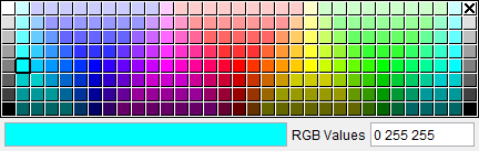
Click on a color in the color palette window, to specify the color for the component. The color palette will close and the right side of the  (Color Palette) icon in the Configure Component menu: Component tab will update to reflect the selected color.
To close the color palette window without changing the color, click on the  in the upper right corner of the color palette.
Default Appearance — Use this option to revert Color choices to the default.
Save as Default — Use this option to save current Color choices as a default.
The remaining features on this tab can be found in Common Features.
The features on the Translate tab enable you to translate the selected object via indicating "from" and "to" points to move the object. Movement occurs each time you press the Move button.
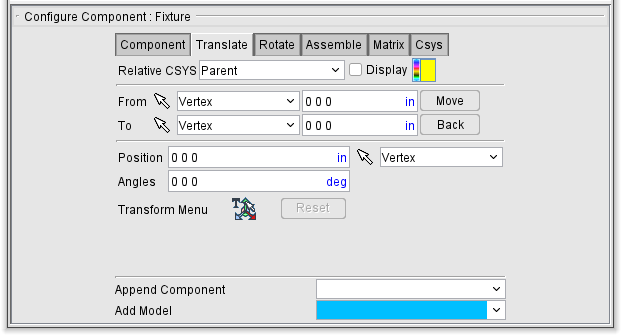
Relative CSYS — Use this pulldown menu to select which CSYS to use. Options include Local, Parent, Machine Origin, Active CSYS, and Program_zero. You can toggle on (check) the adjoining Display checkbox to have the CSYS appear in the Graphics Area. The Color Palette icon next to that checkbox can be used to change the color of the displayed CSYS.
From / To — Use to specify the locations to move the object from and to, relative to the active coordinate system. XYZ values can be entered (separated by spaces), or selected by clicking in the field then clicking on a model. As you move the mouse over the model, a crosshair and vector show you the pending pick-point location. Graphical selection supports picking corner points and midpoints of uncut model geometry, or virtually any point on machined features. The following feature options are available:
-
Vertex — Enables you to select one of six key points associated with the triangles representing the faces of a model. For each triangle, the points consist of the three vertices and the midpoint of each of the triangle's three sides. Optimizer selects the point closest to your mouse pick.
-
Circle Center — Enables you to specify a circle center point. This feature is enabled in the following way:
-
Choose Circle from the pull-down list, and then click the arrow to enable selecting geometry in the graphics area.
-
Follow the prompts in the temporary message area above the Logger panel to define the circle center point.
- Pick the XY plane of the circle.
- Pick the cylinder/cone face that contains the circle.
-
The circle center point will be displayed in the graphics area and the coordinates of the center point will be displayed in the Location text field.
-
3 Planes — Enables you to select a point represented by the intersection of three planes.
-
CSYS Origin — Enables you to select the origin of the chosen coordinate system axis.
-
Component Origin — Enables you to select the origin of a chosen component.
-
Model Origin — Enables you to select the origin of a chosen model.
Move — Moves the selected object by the incremental distance, as calculated from the "From" point to the "To" point location.
Back — Moves the selected object by the incremental distance, as calculated from the "To" point to the "From" point location.
The remaining features on the Translate tab, referred to as “location features”, are common to several Configure Component menu tabs (Rotate, Assemble, Matrix, and Csys) and show the selected object's position and angle, and can be used to move the object or verify its current location. Values are shown relative to the parent component, active Csys, or machine origin depending on the feature that is selected.
Position — Enables you to specify the absolute XYZ position of the object, separated by spaces. This feature also enables you to use feature based selection as described under From/To. Feature based selection is only available when Show Location Relative to Active Csys (csys name) or Relative to Machine Origin is selected.
Angles — Enables you to specify the absolute XYZ rotation of the object, separated by spaces.
Transform menu — Use the  icon to open the Transform Menu window, enabling you to create a transform menu.
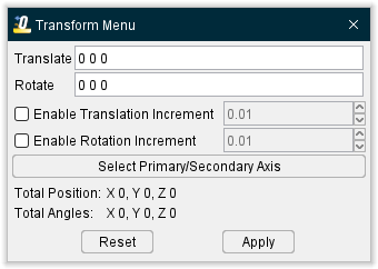
Once the Transform Menu window is open, a new kind of CSYS will appear in the Graphics Area. This axis can be used to manually manipulate the CSYS from the Graphics Area.
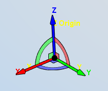
The axis arrows translate the object along the selected axis. A guideline will appear showing you the axis that will be traveled.
The outer rings rotate the object around the central axis. A rotational circle will appear showing you how the object will rotate.
The inner planes translate the object along two adjacent axes. Two guidelines will appear showing you the axes that will be traveled.
The origin snaps the object to the center points, edges, and corners of other objects in the scene.
Translate — Use this field to manually enter the XYZ units you want the CSYS to move by.
Rotate — Use this field to manually enter the XYZ degrees you want the CSYS to rotate by.
Enable Translation Increment — Toggle this feature on (checked) to specify positional movements down to the decimal point. The adjoining dropdown menu will then become active and you can manually enter the number of decimal points or use the arrow bars to increase or decrease the numbers by 0.1.
Enable Rotation Increment — Toggle this feature on (checked) to specify degree rotations down to the decimal point. The adjoining dropdown menu will then become active and you can manually enter the number of decimal points or use the arrow bars to increase or decrease the numbers by 0.1.
Select Primary/Secondary Axis — This button opens the Transform Menu supplemental window enabling you to
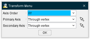
Axis Order — Allows you to specify which axes to give priority. Options include XY, YZ, and ZX.
Primary Axis and Secondary Axis — These enable you to select the vector where the axes will begin from. Use the dropdown menu to select the feature that will form the basis for the axis and then click the mouse pick icon  . Once the mouse pick icon is active, you can then click where you choose on the model in the Graphics Area to set the CSYS to that feature.
OK — Saves your selections and closes the window, returning you to the main Transform Menu window.
Reset — Undoes any changes made and closes the window.
Apply — Saves the changes made.
Reset — Undoes any changes made in the Transform Menu.
Reset — Deletes the created transform menu.
The remaining features on this tab can be found in Common Features.
The features on the Rotate tab enable you to rotate the selected object about a rotation center point. Movement occurs each time you press one of the rotation direction buttons: X+/X-, Y+/Y-, Z+/Z-.
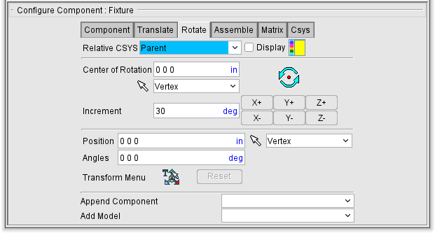
Relative CSYS — Use this pulldown menu to select which CSYS to use. Options include Local, Parent, Machine Origin, Active CSYS, and Program_zero. You can toggle on (check) the adjoining Display checkbox to have the CSYS appear in the Graphics Area. The Color Palette icon next to that checkbox can be used to change the color of the displayed CSYS.
Center of Rotation — Enables you to specify XYZ point location about which to rotate the object. Rotation will always be relative to the active coordinate system. XYZ values can be entered (separated by spaces), or selected by clicking in the field then clicking a position on a model. To see the center of rotation, press  . To remove the center of rotation symbol press the button again, or close the window. You can also use feature based selection to specify the center of rotation. See From/To on the Translate tab for additional information.
Increment — Specifies incremental degrees of rotation to apply when one of the rotation direction buttons are pressed.
Rotation direction buttons — (X+/X-, Y+/Y-, Z+/Z-) When pressed, applies the incremental rotation specified in the Increment field. Rotation occurs about the Center of Rotation, relative to the machine origin.
The remaining features on the Rotate tab, referred to as "location features", are common to all of the following Configure Component menu tabs (Translate, Rotate, Assemble, Matrix, and Csys). They are described in the Configure Component menu, Translate tab section.
The features on the Assemble tab enable you to move the selected object by assembling (mating or aligning) it with other objects. Objects are assembled by mating or aligning one to three planar surfaces with surfaces on other models. If a non-planar surface is selected, Optimizer constructs a tangent plane at the pick point. The relationship of surfaces being mated or aligned is known as a "constraint".
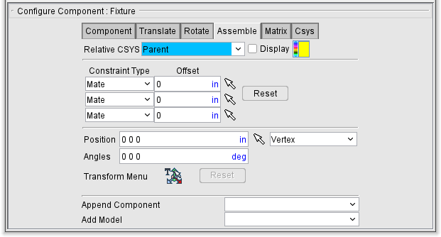
Relative CSYS — Use this pulldown menu to select which CSYS to use. Options include Local, Parent, Machine Origin, Active CSYS, and Program_zero. You can toggle on (check) the adjoining Display checkbox to have the CSYS appear in the Graphics Area. The Color Palette icon next to that checkbox can be used to change the color of the displayed CSYS.
Constraint Type — Specifies how to constrain selected surfaces during object movement. The following is a list of Constraint Type options:
Mate — Moves the object so the selected surface opposes the surface selected on the second object (surface normals oppose each other).
Align — Moves the object so the selected surface is aligned with the surface selected on the second object (surface normals point in the same direction).
Align Cylinder — This feature can be used to align a component, or model, by the axis of a cylinder. The cylinder can be an STL model (if well defined) or a cut model. The cylinder surface can be either an inner surface (hole) or an outer surface (pin).
Follow the prompts in the logger to pick a common plane and two cylinders to align. Note that plane orientation must be same as the cylinder axis.
When second constraint is also Align Cylinder the component or model is rotated about satisfied constraint to achieve closest position of new constraint. The second constraint cannot be satisfied if the distances between holes or pins are different.
Offset — Use to specify a distance and direction (+ or -) in which to offset the constrained surfaces. The offset is applied normal to the surface.
Reset — Use to reset constraints to receive new data.
Follow these general steps to define a constraint for assembly:
-
For each constraint, click on
 , and then select the desired Constraint Type (Mate or Align) from the pull-down list.
 -
Specify an offset for the constraint if desired.
- Click on
 to put the constraint in pick mode so that you can select the surfaces to be constrained. The arrow will become highlighted as shown in the above picture for the second constraint.
 - In the graphics area, select a surface on the object to be moved.
- In the graphics area, select the surface to move the object relative to.
- After selecting the two surfaces to define a constraint, Optimizer moves the object and indicates the satisfied constraint with a checkmark as shown in the picture above for the first constraint.
Mated surfaces — the right side of the green model is mated with the left side of the blue model.
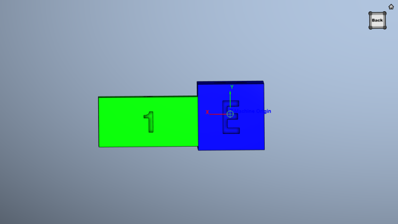
Aligned surfaces — the green block is aligned with the blue block.
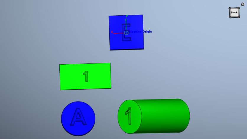
The remaining features on the Assemble tab, referred to as "location features", are common to all of the following Configure Component menu tabs (Translate, Rotate, Assemble, Matrix, and Csys). They are described in the Configure Component menu, Translate tab section.
The features on the Matrix tab enable you to move the selected object via a twelve parameter transformation matrix.
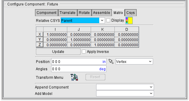
Relative CSYS — Use this pulldown menu to select which CSYS to use. Options include Local, Parent, Machine Origin, Active CSYS, and Program_zero. You can toggle on (check) the adjoining Display checkbox to have the CSYS appear in the Graphics Area. The Color Palette icon next to that checkbox can be used to change the color of the displayed CSYS.
Matrix table — The transformation matrix table is similar to the matrix used in programming APT NC programs. Its twelve parameters reveal the geometric attributes of the local (transformed) coordinate system (CSYS) in terms of the machine origin.
The format of the matrix table is as follows:
| I | J | K | D | |
|---|---|---|---|---|
| X | I1 | J1 | K1 | D1 |
| Y | I2 | J2 | K2 | D2 |
| Z | I3 | J3 | K3 | D3 |
Each row represents an axis of the local CSYS. The first three columns represent the vector associated with each axis: I1, J1, K1 as the positive X-axis vector; I2, J2,K2 as the positive Y-axis vector; and I3, J3, K3 as the positive Z-axis vector. The fourth column values D1, D2, D3 represent the coordinates of the origin point of the local CSYS.
📝 NOTE: If you prefer to see the Matrix Table displayed with the I, J, K along the vertical axis and the X, Y, Z along the horizontal axis, set the environment variable, CGTECH_MATRIX_FORMAT=VERTICAL.
Update — Updates the object location to reflect the matrix table transformation. After updating, press OK or Apply to move the object.
Apply Inverse — When selected, inverts the matrix so that its twelve parameters reveal the geometrical attributes of the machine origin in terms of the local (transformed) coordinate system.
The remaining features on the Matrix tab, referred to as "location features", are common to all of the following Configure Component menu tabs (Translate, Rotate, Assemble, Matrix, and Csys). They are described in the Configure Component menu, Translate tab section.
The features on the Csys tab enable you to translate the selected object from one coordinate system (CSYS) to another. Select the "From" CSYS and the "To" CSYS to move the object. Movement occurs each time you press the Move button.
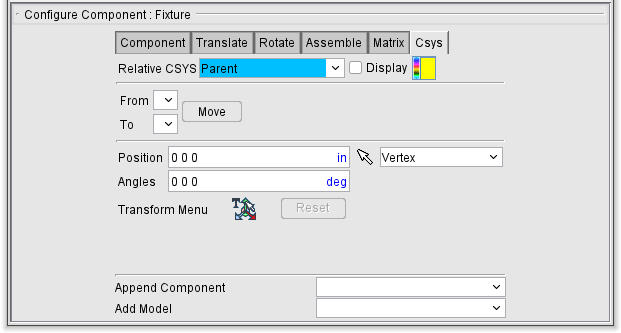
Relative CSYS — Use this pulldown menu to select which CSYS to use. Options include Local, Parent, Machine Origin, Active CSYS, and Program_zero. You can toggle on (check) the adjoining Display checkbox to have the CSYS appear in the Graphics Area. The Color Palette icon next to that checkbox can be used to change the color of the displayed CSYS.
From / To — Specifies the coordinate system to move the object from, and to. Select the appropriate CSYS from each of the pull-down lists.
Move — Moves the selected object from the "From" CSYS to the "To" CSYS orientation.
The remaining features on the Csys tab, referred to as "location features", are common to all of the following Configure Component menu tabs (Translate, Rotate, Assemble, Matrix, and Csys). They are described in the Configure Component menu, Translate tab section.
Configure Stock
Component tab
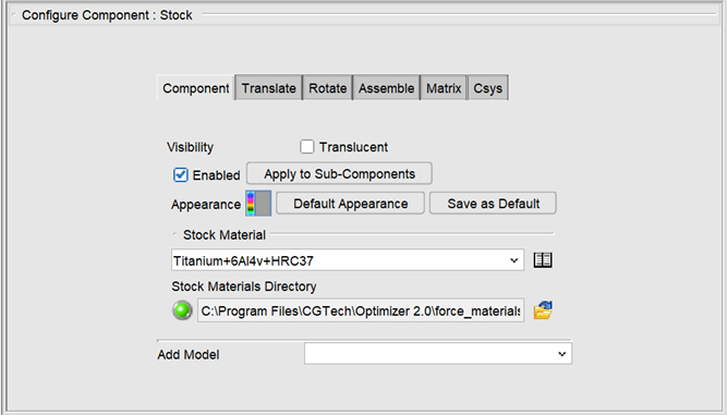
Component tab — Features on the Component tab are used to define the attributes of a component. Otpimizer handles components and their solid models differently depending on the component's type and attributes. Most attributes apply to components used in building NC machines.
Stock Material — This field lists the type of material that is used for stock in this project. Stock Material can be changed through the Stock Material Catalog which can be opened by clicking the Choose From Catalog button. This opens the Stock Material Catalog window, enabling you to select Stock Materials for your project from a pre-generated list of options.
Stock Material Catalog — This window enables you to search through all available material options for your stock materials. Use the ISO Group or Filter option at the top to find the Stock Material Name, Tool Material, or Tool Edge Type you are looking for. You can toggle between View Stock Materials and View Stock and Tool Info to see different levels of information about each material. Once you have highlighted your material, click Save As Optimize Stock Material to implement your selection.
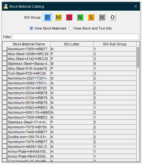
📝 NOTE: The Stock Material options only appear when in the Configure Component: Stock menu.
Stock Materials Directory — This field lists the filepath to reference Stock Materials. Use the browse icon ( ) to open the file selection folder to select your pathway. A green light indicates that the pathway is good.
The remaining features are described in the Configure Component menu, Translate tab section.
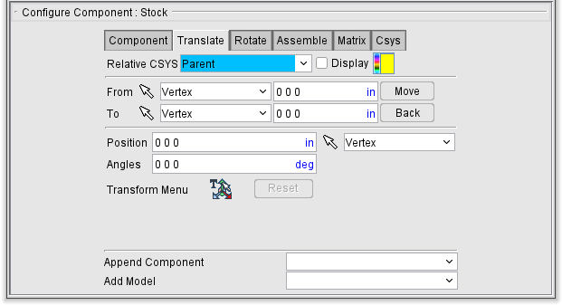
Relative CSYS — Use this pulldown menu to select which CSYS to use. Options include Local, Parent, Machine Origin, Active CSYS, and Program_zero. You can toggle on (check) the adjoining Display checkbox to have the CSYS appear in the Graphics Area. The Color Palette icon next to that checkbox can be used to change the color of the displayed CSYS.
From / To — Use to specify the locations to move the object from and to, relative to the active coordinate system. XYZ values can be entered (separated by spaces), or selected by clicking in the field then clicking on a model. As you move the mouse over the model, a crosshair and vector show you the pending pick-point location. Graphical selection supports picking corner points and midpoints of uncut model geometry, or virtually any point on machined features. The following feature options are available:
Vertex — Enables you to select one of six key points associated with the triangles representing the faces of a model. For each triangle, the points consist of the three vertices and the midpoint of each of the triangle's three sides. Optimizer selects the point closest to your mouse pick.
Circle Center — Enables you to specify a circle center point. This feature is enabled in the following way:
- Choose Circle from the pull-down list, and then click the arrow to enable selecting geometry in the graphics area.
- Follow the prompts in the temporary message area above the Logger panel to define the circle center point.
- Pick the XY plane of the circle.
- Pick the cylinder/cone face that contains the circle.
- The circle center point will be displayed in the graphics area and the coordinates of the center point will be displayed in the Location text field.
3 Planes — Enables you to select a point represented by the intersection of three planes.
CSYS Origin — Enables you to select the origin of the chosen coordinate system axis.
Component Origin — Enables you to select the origin of a chosen component.
Model Origin — Enables you to select the origin of a chosen model.
Move — Moves the selected object by the incremental distance, as calculated from the "From" point to the "To" point location.
Back — Moves the selected object by the incremental distance, as calculated from the "To" point to the "From" point location.
The remaining features on the Translate tab, referred to as “location features”, are common to several Configure Component menu tabs (Rotate, Assemble, Matrix, and Csys) and show the selected object's position and angle, and can be used to move the object or verify its current location. Values are shown relative to the parent component, active Csys, or machine origin depending on the feature that is selected.
Position — Enables you to specify the absolute XYZ position of the object, separated by spaces. This feature also enables you to use feature based selection as described under From/To. Feature based selection is only available when Show Location Relative to Active Csys (csys name) or Relative to Machine Origin is selected.
Angles — Enables you to specify the absolute XYZ rotation of the object, separated by spaces.
Transform menu — Use the icon to open the Transform Menu window, enabling you to create a transform menu.
Once the Transform Menu window is open, a new kind of CSYS will appear in the Graphics Area. This axis can be used to manually manipulate the CSYS from the Graphics Area.
The axis arrows translate the object along the selected axis. A guideline will appear showing you the axis that will be traveled.
The outer rings rotate the object around the central axis. A rotational circle will appear showing you how the object will rotate.
The inner planes translate the object along two adjacent axes. Two guidelines will appear showing you the axes that will be traveled.
The origin snaps the object to the center points, edges, and corners of other objects in the scene.
Translate — Use this field to manually enter the XYZ units you want the CSYS to move by.
Rotate — Use this field to manually enter the XYZ degrees you want the CSYS to rotate by.
Enable Translation Increment — Toggle this feature on (checked) to specify positional movements down to the decimal point. The adjoining dropdown menu will then become active and you can manually enter the number of decimal points or use the arrow bars to increase or decrease the numbers by 0.1.
Enable Rotation Increment — Toggle this feature on (checked) to specify degree rotations down to the decimal point. The adjoining dropdown menu will then become active and you can manually enter the number of decimal points or use the arrow bars to increase or decrease the numbers by 0.1.
Select Primary/Secondary Axis — This button opens the Transform Menu supplemental window enabling you to
Axis Order — Allows you to specify which axes to give priority. Options include XY, YZ, and ZX.
Primary Axis and Secondary Axis — These enable you to select the vector where the axes will begin from. Use the dropdown menu to select the feature that will form the basis for the axis and then click the mouse pick icon . Once the mouse pick icon is active, you can then click where you choose on the model in the Graphics Area to set the CSYS to that feature.
OK — Saves your selections and closes the window, returning you to the main Transform Menu window.
Reset — Undoes any changes made and closes the window.
Apply — Saves the changes made.
Reset — Undoes any changes made in the Transform Menu.
Reset — Deletes the created transform menu.
The remaining features on this tab can be found in Common Features.
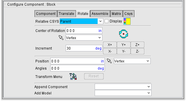
Relative CSYS — Use this pulldown menu to select which CSYS to use. Options include Local, Parent, Machine Origin, Active CSYS, and Program_zero. You can toggle on (check) the adjoining Display checkbox to have the CSYS appear in the Graphics Area. The Color Palette icon next to that checkbox can be used to change the color of the displayed CSYS.
Center of Rotation — Enables you to specify XYZ point location about which to rotate the object. Rotation will always be relative to the active coordinate system. XYZ values can be entered (separated by spaces), or selected by clicking in the field then clicking a position on a model. To see the center of rotation, press . To remove the center of rotation symbol press the button again, or close the window. You can also use feature based selection to specify the center of rotation. See From/To on the Translate tab for additional information.
Increment — Specifies incremental degrees of rotation to apply when one of the rotation direction buttons are pressed.
Rotation direction buttons — (X+/X-, Y+/Y-, Z+/Z-) When pressed, applies the incremental rotation specified in the Increment field. Rotation occurs about the Center of Rotation, relative to the machine origin.
The remaining features on the Rotate tab, referred to as "location features", are common to all of the following Configure Component menu tabs (Translate, Rotate, Assemble, Matrix, and Csys). They are described in the Configure Component menu, Translate tab section.
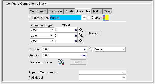
Relative CSYS — Use this pulldown menu to select which CSYS to use. Options include Local, Parent, Machine Origin, Active CSYS, and Program_zero. You can toggle on (check) the adjoining Display checkbox to have the CSYS appear in the Graphics Area. The Color Palette icon next to that checkbox can be used to change the color of the displayed CSYS.
Constraint Type — Specifies how to constrain selected surfaces during object movement. The following is a list of Constraint Type options:
Mate — Moves the object so the selected surface opposes the surface selected on the second object (surface normals oppose each other).
Align — Moves the object so the selected surface is aligned with the surface selected on the second object (surface normals point in the same direction).
Align Cylinder — This feature can be used to align a component, or model, by the axis of a cylinder. The cylinder can be an STL model (if well defined) or a cut model. The cylinder surface can be either an inner surface (hole) or an outer surface (pin).
Follow the prompts in the logger to pick a common plane and two cylinders to align. Note that plane orientation must be same as the cylinder axis.
When second constraint is also Align Cylinder the component or model is rotated about satisfied constraint to achieve closest position of new constraint. The second constraint cannot be satisfied if the distances between holes or pins are different.
Offset — Use to specify a distance and direction (+ or -) in which to offset the constrained surfaces. The offset is applied normal to the surface.
Reset — Use to reset constraints to receive new data.
Follow these general steps to define a constraint for assembly:
-
For each constraint, click on
, and then select the desired Constraint Type (Mate or Align) from the pull-down list. -
Specify an offset for the constraint if desired.
- Click on to put the constraint in pick mode so that you can select the surfaces to be constrained. The arrow will become highlighted as shown in the above picture for the second constraint.
- In the graphics area, select a surface on the object to be moved.
- In the graphics area, select the surface to move the object relative to.
- After selecting the two surfaces to define a constraint, Optimizer moves the object and indicates the satisfied constraint with a checkmark as shown in the picture above for the first constraint.
Mated surfaces — the right side of the green model is mated with the left side of the blue model.
Aligned surfaces — the green block is aligned with the blue block.
The remaining features on the Assemble tab, referred to as "location features", are common to all of the following Configure Component menu tabs (Translate, Rotate, Assemble, Matrix, and Csys). They are described in the Configure Component menu, Translate tab section.
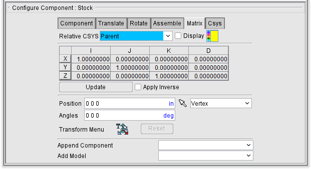
Relative CSYS — Use this pulldown menu to select which CSYS to use. Options include Local, Parent, Machine Origin, Active CSYS, and Program_zero. You can toggle on (check) the adjoining Display checkbox to have the CSYS appear in the Graphics Area. The Color Palette icon next to that checkbox can be used to change the color of the displayed CSYS.
Matrix table — The transformation matrix table is similar to the matrix used in programming APT NC programs. Its twelve parameters reveal the geometric attributes of the local (transformed) coordinate system (CSYS) in terms of the machine origin.
The format of the matrix table is as follows:
| I | J | K | D | |
|---|---|---|---|---|
| X | I1 | J1 | K1 | D1 |
| Y | I2 | J2 | K2 | D2 |
| Z | I3 | J3 | K3 | D3 |
Each row represents an axis of the local CSYS. The first three columns represent the vector associated with each axis: I1, J1, K1 as the positive X-axis vector; I2, J2,K2 as the positive Y-axis vector; and I3, J3, K3 as the positive Z-axis vector. The fourth column values D1, D2, D3 represent the coordinates of the origin point of the local CSYS.
📝 NOTE: If you prefer to see the Matrix Table displayed with the I, J, K along the vertical axis and the X, Y, Z along the horizontal axis, set the environment variable, CGTECH_MATRIX_FORMAT=VERTICAL.
Update — Updates the object location to reflect the matrix table transformation. After updating, press OK or Apply to move the object.
Apply Inverse — When selected, inverts the matrix so that its twelve parameters reveal the geometrical attributes of the machine origin in terms of the local (transformed) coordinate system.
The remaining features on the Matrix tab, referred to as "location features", are common to all of the following Configure Component menu tabs (Translate, Rotate, Assemble, Matrix, and Csys). They are described in the Configure Component menu, Translate tab section.
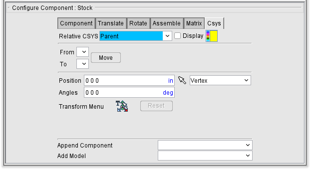
Relative CSYS — Use this pulldown menu to select which CSYS to use. Options include Local, Parent, Machine Origin, Active CSYS, and Program_zero. You can toggle on (check) the adjoining Display checkbox to have the CSYS appear in the Graphics Area. The Color Palette icon next to that checkbox can be used to change the color of the displayed CSYS.
From / To — Specifies the coordinate system to move the object from, and to. Select the appropriate CSYS from each of the pull-down lists.
Move — Moves the selected object from the "From" CSYS to the "To" CSYS orientation.
The remaining features on the Csys tab, referred to as "location features", are common to all of the following Configure Component menu tabs (Translate, Rotate, Assemble, Matrix, and Csys). They are described in the Configure Component menu, Translate tab section.
Configure Models
This section is not to be confused with the Configure Model section which is the child branch of this menu.
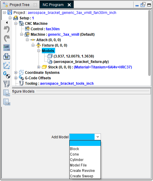
Add Model —The Add Model pull-down list contains the model types that can be added to a component. Click on the arrow button and select from the following model types:
Block — Selecting Block adds a default block model to the Project Tree and displays the Configure Model menu with Type set to "Block" enabling you to define the block's attributes and position. You can then set the Length (X), Width (Y), and Height (Z) of the block in the Configure Model menu. There are also options to set Edge Angles and Appearance.
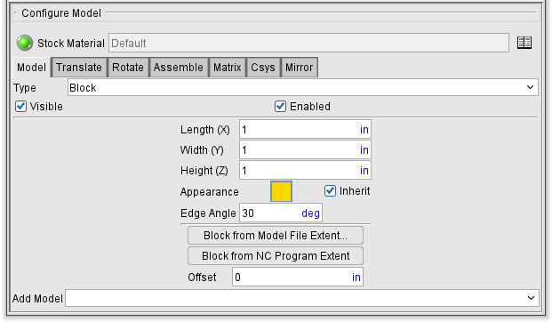
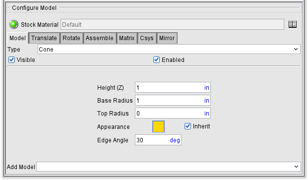
Cone — Selecting Cone adds a default cone model to the Project Tree and displays the Configure Model menu with Type set to "Cone” enabling you to define the cone's attributes and position. You can then set the Height (Z), Base Radius, and Top Radius in the Configure Model menu. There are also options to set Edge Angles and Appearance.
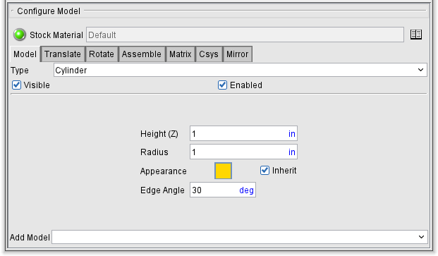
Cylinder — Selecting Cylinder adds a default cylinder model to the Project Tree and displays the Configure Model menu with Type set to "Cylinder" enabling you to define the cylinder’s attributes and position. You can then set the Height (Z) and Radius in the Configure Model menu. There are also options to set Edge Angles and Appearance.
Model File — Selecting Model File displays the Open file selection window enabling you to specify the model file to add to the Project Tree. Once the model file is added to the Project Tree the Configure Model menu displays with Type set to "Model File" model's position.
Create Revolve — Selecting Create Revolve opens the Profile Sketcher window in "solid of revolution" mode.
Create Sweep — Selecting Create Sweep opens the Profile Sketcher window in "sweep solid" mode.
Create Sweep and Create Revolve open the appropriate sketcher dialog. Once the sketch is created, the file saved, the model is added and selected in the tree when the sketcher dialog is closed.
📝 NOTE: Add Model is not available when an Attach component is selected in the Project Tree and the Show Machine Components feature is toggled "off" or not available at all.
Configure Model
This section is not to be confused with the Configure Models section which is the parent branch of this menu.
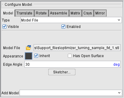
Model tab
Model File — Displays the model file pathway. Use the browse button to designated a new pathway.
Appearance — Use to set the color of the model. Toggle on Inherit (checked) to make the appearance the same as its parent.
Has Open Surface — Toggle on (checked) to indicate when a model file has Open Surface.
Edge Angle — Use to set the angle of the model.
Sketcher — Use to open the Profile Sketcher window.
This section is identical to Configure Stock, Translate tab.
This section is identical to Configure Stock, Rotate tab.
This section is identical to Configure Stock, Assemble tab.
This section is identical to Configure Stock, Matrix tab.
This section is identical to Configure Stock, Csys tab.
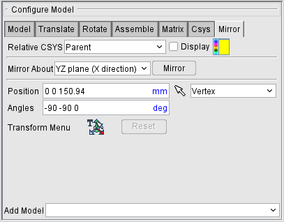
Mirror About — Use to indicate whether the model will be mirrored along the YZ plane, ZX plane, or XY plane. Once you have decided on your plane, hit the Mirror button to see the mirroring in aciton.
The remaining features on this menu are common Transform menu features.
Configure Coordinate System
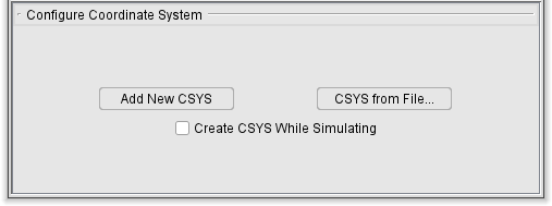
These features are also present in Configuring CSYS menus:
Add New CSYS — Creates a CSYS to manipulate. See next section for in depth information on configuring CSYS.
CSYS from File — Opens a file selection window enabling you to import an already saved CSYS file.
Create CSYS While Simulating — When this option is toggled on (checked), a CSYS while automatically generate while your simulation is playing.
Configure CSYS
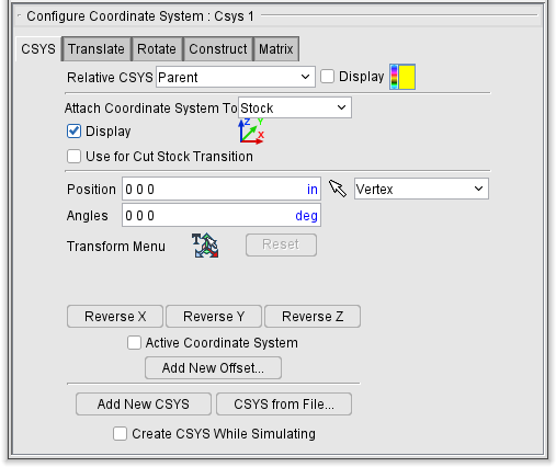
Relative CSYS — Use this pulldown menu to select which CSYS to use. Options include Local, Parent, Machine Origin, Active CSYS, and Program_zero. You can toggle on (check) the adjoining Display checkbox to have the CSYS appear in the Graphics Area. The Color Palette icon next to that checkbox can be used to change the color of the displayed CSYS.
Attach Coordinate System To — Enables you to attach a CSYS to a particular component so that if the component gets repositioned, the CSYS also gets repositioned, maintaining the defined relationship. Select the component from the pull-down list.
📝 NOTE: This feature is not applicable to the Tool Manager, Configure Coordinate Systems menu.
Display — Toggle this feature on (checked) to cause the CSYS to be visible in the Graphics Area.
 (Color Palette)— The Color Palette icon enables you to override the "global" coordinate system to choose the display color for the CSYS. The right side of the Color Palette icon shows the current color for the coordinate system. To change the color for the coordinate system, click on the (Color Palette) icon to display the color palette window shown below.
Click on the color in the color palette window, to specify the color for the coordinate system. The color palette window will close and the right side of the (Color Palette) icon in the Configure Coordinate System menu: CSYS tab will update to reflect the selected color.
To close the color palette window without changing the color, click on the  in the upper right corner of the color palette window.
Use for Cut Stock Transition — Use to designate that the coordinate system is used for transitioning the cut stock(s) from one setup position to another. Stock transition coordinate systems can be created for each Stock component.
The following features enable you to override the "global" visibility and color characteristics, set with Project tab > View Axes window: Coordinate Systems, for the individual coordinate system currently selected in the Project Tree.
📝 NOTE: This feature is not applicable to the Tool Manager, Configure Coordinate Systems menu.
Reverse X — Reverses the X axis of the "active" coordinate system. (See note below)
Reverse Y — Reverses the Y axis of the "active" coordinate system. (See note below)
Reverse Z — Reverses the Z axis of the "active" coordinate system. (See note below)
📝 NOTE: In order to maintain a right handed csys, the following will occur when an axis is reversed:
If the X axis is reversed, then the Z axis is also reversed.
If the Y axis is reversed, then the X axis is also reversed.
If the Z axis is reversed, then the Y axis is also reversed.
Active Coordinate System — Toggle "on" (checked) the Active Coordinate System feature to designate the coordinate system currently highlighted in the Project Tree to be the "active" coordinate system.
📝 NOTE: This feature is not applicable to the Tool Manager, Configure Coordinate Systems menu.
Add New Offset — Opens Configure G-Code Offsets menu, enabling you to designate G-Code Offsets.
The location and transform features are common to all Configure CSYS menu tabs. They are described in the Configure Component menu, Translate tab section.
The add CSYS features are common to all Configure CSYS menu tabs. They are described in the Coordinate System section.
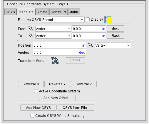
Relative CSYS — Use this pulldown menu to select which CSYS to use. Options include Local, Parent, Machine Origin, Active CSYS, and Program_zero. You can toggle on (check) the adjoining Display checkbox to have the CSYS appear in the Graphics Area. The Color Palette icon next to that checkbox can be used to change the color of the displayed CSYS.
From / To — Use the From and To text fields to specify the "from" point, and the "to" point, to be used for moving the CSYS. XYZ values can be entered (separated by spaces), or selected by clicking in the field then clicking on a model. As you move the mouse over the model, a crosshair and vector show you the pending pick-point location. Graphical selection supports picking corner points and midpoints of uncut model geometry, or virtually any point on machined features or tool assembly features.
When working in the Project Tree, Configure Coordinate System menu the From and To points are relative to the workpiece origin.
When working in the Tool Manager, Configure Coordinate System menu, the From and To points are relative to the tool origin.
Move — Moves the selected CSYS by the incremental distance, as calculated from the "From" point to the "To" point location.
Back — Moves the selected CSYS by the incremental distance, as calculated from the "To" point to the "From" point location.
Local Translation — When toggled "on", From/To values are relative to the current CSYS.
📝 NOTE: This feature is useful when trying to align a CSYS to the center of a machined hole.
Position CSYS at Component Origin — Enables you to position the origin of the coordinate system currently selected in the Project Tree at the origin of the selected component.
Click on the icon to enable you to pick a component in the graphics area. Once you have clicked on the icon, the Position field becomes highlighted in yellow and the component origin will display in the graphics area when the mouse pointer is held over a component. Selecting a component in the graphics area sets the Position field to the coordinates of the selected component’s origin and the origin of coordinate system that is selected currently selected in the Project Tree will be repositioned to the coordinates.
📝 NOTE: This feature is not applicable to the Tool Manager, Configure Coordinate Systems menu.
The location and transform features are common to all Configure CSYS menu tabs. They are described in the Configure Component menu, Translate tab section.
The add CSYS features are common to all Configure CSYS menu tabs. They are described in the Coordinate System section.
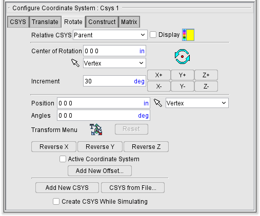
Relative CSYS — Use this pulldown menu to select which CSYS to use. Options include Local, Parent, Machine Origin, Active CSYS, and Program_zero. You can toggle on (check) the adjoining Display checkbox to have the CSYS appear in the Graphics Area. The Color Palette icon next to that checkbox can be used to change the color of the displayed CSYS.
Center of Rotation — Specifies XYZ point location about which to rotate the CSYS. XYZ values can be entered (separated by spaces), or selected by clicking in the field then clicking on a model. To see the center of rotation, press  . To remove the center of rotation symbol press the button again, or close the Coordinate System window.
Increment — Specifies incremental degrees of rotation to apply when one of the rotation direction buttons are pressed.
Rotation direction buttons — (X+/X-, Y+/Y-, Z+/Z-) When pressed, applies the incremental rotation specified in the Increment field. Rotation occurs about the Center of Rotation, relative to the Attach Component's CSYS.
Local Rotation — When toggled "on", the incremental rotation values are relative to the current CSYS.
📝 NOTE: This feature is useful when trying to align a CSYS to the center of a machined hole.
The location and transform features are common to all Configure CSYS menu tabs. They are described in the Configure Component menu, Translate tab section.
The add CSYS features are common to all Configure CSYS menu tabs. They are described in the Coordinate System section.
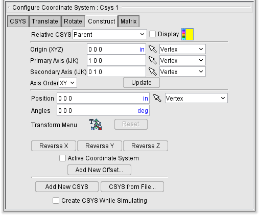
Relative CSYS — Use this pulldown menu to select which CSYS to use. Options include Local, Parent, Machine Origin, Active CSYS, and Program_zero. You can toggle on (check) the adjoining Display checkbox to have the CSYS appear in the Graphics Area. The Color Palette icon next to that checkbox can be used to change the color of the displayed CSYS.
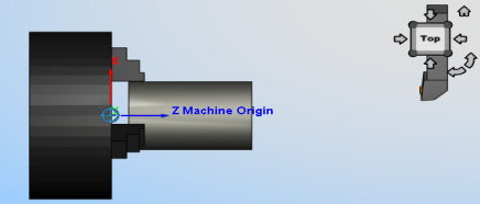
While the Construct tab is active, a marker is displayed in the graphics area (see the picture below) showing the current position/orientation of the axis being constructed based on the Construct tab settings. The display is updated each time you change a value on the Construct tab. The marker is automatically clears when you leave the Construct tab.
Origin (XYZ) — Use these features to define a point representing the origin of the CSYS.
Primary Axis (IJK) — Use these features to define a point or vector representing the direction of the CSYS primary axis.
Secondary Axis (IJK) — Use these features to define a point or vector representing the direction of the CSYS secondary axis.
For each of the items above, you can either enter the coordinates of the point, separated by spaces, in the text field or select one of the construction methods and pick geometry in the graphics area to define the item. Choose one of the construction methods from the pull-down list, then click the arrow
and follow the prompts in the message area to define the item. The following construction methods are available:
Point — Use to select a point.
Vector/Plane — Define a point represented by the intersection of a vector with a plane.
3 Planes — Define a point represented by the intersection of three planes.
Circle — Define a point represented by the center of a circle.
-
Choose Circle from the pull-down list, and then click the arrow
to enable selecting geometry in the graphics area. -
Follow the prompts in the temporary message area above the Logger panel to define the circle center point.
- Pick the XY plane of the circle.
- Pick the cylinder/cone face that contains the circle.
- The circle center point will display in the graphics area and the coordinates of the center point will display in the text field of the entity that you are currently describing on the Construct tab.
CSYS Origin — Define a point represented by the origin of an existing coordinate system.
📝 NOTE: When using one of the point construction methods to define the Primary or Secondary Axis, the origin is subtracted from the generated point to define the direction vector representing the axis.
Vector — Define the direction of a CSYS axis by selecting a vector. (not available for Origin)
Plane/Plane — Define the direction of a CSYS axis by a vector represented by the intersection of two planes. (not available for Origin)
Axis Order — Choose from the pull-down list to assign X, Y or Z to the Primary and Secondary axes of the CSYS.
XY — assigns the Primary Axis to be X and the Secondary Axis to be Y.
YZ — assigns the Primary Axis to be Y and the Secondary Axis to be Z.
ZX — assigns the Primary Axis to be Z and the Secondary Axis to be X.
Update — Use the values selected above to update an existing CSYS, or create a new CSYS. When the Update button is pressed the following occurs:
-
The Primary Axis and the Secondary Axis are crossed to determine the third axis.
-
The third axis is then crossed with the Primary Axis to ensure that the Secondary Axis is orthogonal.
- The CSYS currently active in the Coordinate System window is updated with the resultant orthogonal coordinate system and the origin. If no CSYS is currently active, Optimizer creates a new CSYS and automatically assigns it a unique name.
The location and transform features are common to all Configure CSYS menu tabs. They are described in the Configure Component menu, Translate tab section.
The add CSYS features are common to all Configure CSYS menu tabs. They are described in the Coordinate System section.
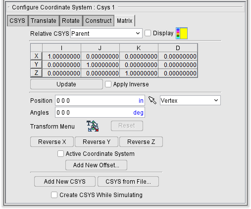
Relative CSYS — Use this pulldown menu to select which CSYS to use. Options include Local, Parent, Machine Origin, Active CSYS, and Program_zero. You can toggle on (check) the adjoining Display checkbox to have the CSYS appear in the Graphics Area. The Color Palette icon next to that checkbox can be used to change the color of the displayed CSYS.
Matrix Table — The transformation matrix table is similar to the matrix used in programming APT tool paths. Its twelve parameters reveal the geometrical attributes of the local (transformed) coordinate system (CSYS) in terms of the workpiece origin.
The format of the matrix table is as follows:
| I | J | K | D | |
|---|---|---|---|---|
| X | I1 | J1 | K1 | D1 |
| Y | I2 | J2 | K2 | D2 |
| Z | I3 | J3 | K3 | D3 |
Each row represents an axis of the local CSYS. The first three columns represent the vector associated with each axis: I1, J1, K1 as the positive X-axis vector; I2, J2,K2 as the positive Y-axis vector; and I3, J3, K3 as the positive Z-axis vector. The fourth column values D1, D2, D3 represent the coordinates of the origin point of the local CSYS.
📝 NOTE: If you prefer to see the Matrix Table displayed with the I, J, K along the vertical axis and the X, Y, Z along the horizontal axis, set the environment variable, CGTECH_MATRIX_FORMAT=VERTICAL.
Update — Updates the CSYS location to reflect the matrix table transformation.
Apply Inverse On Update — When selected, inverts the matrix so that its twelve parameters reveal the geometrical attributes of the workpiece origin in terms of the local (transformed) coordinate system.
The location and transform features are common to all Configure CSYS menu tabs. They are described in the Configure Component menu, Translate tab section.
The add CSYS features are common to all Configure CSYS menu tabs. They are described in the Coordinate System section.
Configure G-Code Offsets
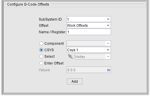
SubSystem ID — Use to specify ID of the machine subsystem for which the table is being defined.
Offset — Use to identify the type of offset table to be added, or modified, if it already exists. Choose one of the following offset table types from the pull-down list.
Base Work Offset — The Base Work Offset table specifies the location from which work offsets are based. Use this table when the NC program file references a base work coordinate system (e.g. G52) from which all other work offsets are based..
Work Offsets — The Work Offsets table stores work coordinate system offset, or "fixture offset" values. Use this table when simulating programming with work offsets (e.g. G53-59). Enter values to represent the work offset values entered at the NC control. Work coordinate system offset values that are automatically loaded using data in the NC program file (e.g. G10L2Pn) do not require entry.
Shift Offsets — The Shift Offsets table stores work coordinate system offsets similar to Work Offsets.
Program Zero — The Program Zero table is used to specify the programmed zero location of a G-Code NC program file taking Tool Length Compensation into consideration. This table is required when the machine operator establishes a zero location other than machine zero. This activity is also known as establishing a "floating zero" location.
Name/Register — The name or Register number that will be used by Optimizer to access corresponding table data. The Register number may correspond to an offset register number, or an integer value, as required by a particular table. The user can enters text similar to what is defined in the NC program. It could be G54, G54.2P5, G500, or just a register number.
📝 NOTE: Optimizer knows what G54/G54.2P5 stand for (work offset and secondary work offset) and it will automatically define the table based on what is define in the control file.
📝 NOTE: The user can still enter just the Register number.
The following features are mutually exclusive selections that can be toggled between to place your G-Code Offsets.
Component — Use this field to specify which component your G-Code Offset will be associated with. Example components include Stock, Fixtures, and so on.
CSYS — Use this field to associate your G-Code Offset with an active coordinate system.
Select — Select this toggle to associate your G-Code Offset by manually clicking in the Graphics Display Area. Click the icon to enable mouse selection. Use the dropdown menu to select which features the mouse click will associate the G-Code Offset to. Potential examples include Vertex, Circle Center, 3 Planes, CSYS Origin, Component Origin, and Model Origin.
Enter Offset — Use this field to manually enter the X Y Z values you want the G-Code Offset associated with.
Add — this button is used to introduce a new offset table to the Project Tree with a default table record highlighted. The Configure Work Offsets menu is automatically displayed enabling you to specify values for the record. If the offset table of the same type already exists, an error message is output.
Configure Work Offsets
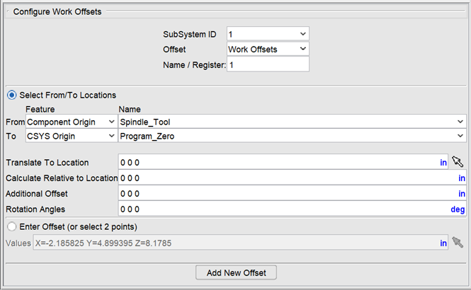
SubSystem ID — Use to specify ID of the machine subsystem for which the table is being defined.
Offset — Use to identify the type of offset table to be added, or modified, if it already exists. Choose one of the following offset table types from the pull-down list.
Base Work Offset — The Base Work Offset table specifies the location from which work offsets are based. Use this table when the NC program file references a base work coordinate system (e.g. G52) from which all other work offsets are based..
Work Offsets — The Work Offsets table stores work coordinate system offset, or "fixture offset" values. Use this table when simulating programming with work offsets (e.g. G53-59). Enter values to represent the work offset values entered at the NC control. Work coordinate system offset values that are automatically loaded using data in the NC program file (e.g. G10L2Pn) do not require entry.
Shift Offsets — The Shift Offsets table stores work coordinate system offsets similar to Work Offsets.
Program Zero — The Program Zero table is used to specify the programmed zero location of a G-Code NC program file taking Tool Length Compensation into consideration. This table is required when the machine operator establishes a zero location other than machine zero. This activity is also known as establishing a "floating zero" location.
Name/Register — The name or Register number that will be used by Optimizer to access corresponding table data. The Register number may correspond to an offset register number, or an integer value, as required by a particular table. The user can enters text similar to what is defined in the NC program. It could be G54, G54.2P5, G500, or just a register number.
📝 NOTE: Optimizer knows what G54/G54.2P5 stand for (work offset and secondary work offset) and it will automatically define the table based on what is define in the control file.
📝 NOTE: The user can still enter just the Register number.
Select From/To Locations — Enables you to specify table values based on a "relational" offset between a "from" point and a "to" point. The "from" and "to" points are designated by specifying a particular component or CSYS. Optimizer will use the origin of the component/CSYS as the point. You can also specify an offset from the specified component/CSYS origin point. Once this relationship has been established, you can change the machine configuration or the location of the CSYS origin and the table values will updated automatically during the initial Single Step or during Play to End.
For example: After Input Program Zero has been defined to be the offset from the Tool Component to the "Program Zero" CSYS, you can change the machine configuration, or change the location of "Program Zero" CSYS, and the Input Program Zero offset values will be updated automatically during the initial Single Step or during Play to End.
📝 NOTE: The offsets are calculated based on where the corresponding origin points are located when all linear axes are driven to machine zero (zero with no offsets in place).
Select From/To Locations section
When Select From/To Locations is toggled "On", the From/To Feature/Name lists and the Offset text fields become activated. Use the From/To Feature lists to specify whether the point is associated with a Component or a CSYS (coordinate system). Use the From/To Name lists to specify a specific component or coordinate system.
📝 NOTE: Only the coordinate systems that have been defined with reference to a machine component (i.e., visible in a Machine view when Coordinate System axis is toggled "on") will appear in the CSYS/Names lists.
Translate To Location — Use this text field to enter 3 values, separated by spaces, representing the X, Y, and Z offset from the specified origin point. You can also click on the "select" button , then pick a point in the graphics display area. You can pick the point in either a workpiece or machine view. Optimizer will calculate the Translate To Location value between the selected point and the designated origin point.
Calculate Relative to Location — This feature enables you to have a relational offset recalculated in the machine position where the offset will be used. The new position is immediately calculated and stored and therefore is not dependent on the machine position when the offset is activated.
Additional Offset — Use this text field to specify an additional offset value.
Rotation Angles — Use this text field to enter 3 values separated by spaces, representing the X, Y, and Z degrees of offset in terms of rotation.
Enter Offset (or select 2 points) — when toggled "On", the Values (XYZABCUVWABC) text field is activated enabling you to enter between 1 and 12 values corresponding to various axes of the program to set your own offset. You can also enter words as values.
The WORD/VALUE format has the following rules:
-
Valid Words are: X, Y, Z, A, B, C, U, V, W, AA, BB, CC
-
Mixed formats are not allowed. You can use either the Traditional format, or the WORD/VALUE format.
- The Words can be entered in any order.
- You only need to specify words with non-zero values.
- If a word is specified twice, the last value specified will be used.
- If all values are zero, you can leave the field blank. In this case, the display will be X0 Y0 Z0.
You can also click on the "select" button , then pick two points in the graphics display area. You can pick the points in either a workpiece or machine view. Optimizer will calculate the Offset value between the selected points.
Add — this button is used to introduce a new offset table to the Project Tree with a default table record highlighted.
Configure Base Work Offsets
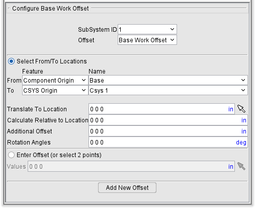
The features for this menu are identical to Work Offsets.
Configure Shift Offsets
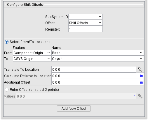
The features for this menu are identical to Work Offsets.
Configure Program Zero
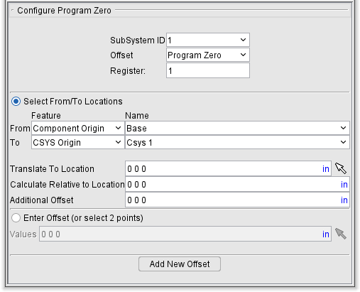
The features for this menu are identical to Work Offsets.
Configure Tooling
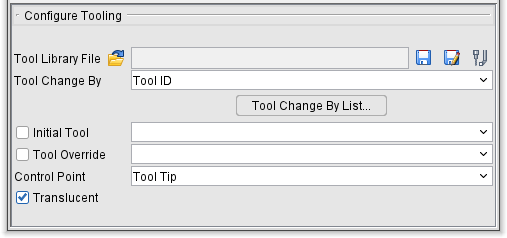
Tool Library File — The Tool Library File features enable you to open an existing, and save the current Tool Library file. The /path/filename of the current Tool Library file is displayed.
(Open File) — Use to open an existing Tool Library file. Use the file selection window that displays to select the desired Tool Library file. Most features on this window are standard file selection window features that enable you to navigate through directories, filter files, and type, or select, /path/filenames.
(Save File) — Saves (updates) the current Tool Library file. Optimizer will save the Tool Library file if you have sufficient permissions to save the file in its present folder. Otherwise, the Save Project File As window will display enabling you to specify a location to save where you have write permissions.
(Save As File) — Opens the Save As File window enabling you to save the current Tool Library file with a new name or in a new location. Most features on this window are standard file selection window features that enable you to navigate through directories, filter files, and type, or select, /path/filenames.
 (Tools) — Opens the Tool Manager window enabling you to create and maintain Tool Library files containing descriptions of cutting tools, or tool assemblies.
Tool Change By — Controls how Optimizer receives descriptions of cutting tools.
Cutter Desc. — Process parametric cutter descriptions in the NC program file. Examples: CUTTER and Vericut-TC comment records.
Vericut TC — Process by PPRINT/Vericut-TC cutter statements in the NC program file.
Tool ID — Process NC program records that reference tool or pocket numbers and retrieve associated tools from a Tool Library file. Examples: TnM6 (G-Code NC programs), LOADTL or LOAD TOOL, and TURRET. When using Tool Change by Tool Number, The tool number is matched with the pocket number (ex: tool #5 in pocket #5).
List — Processes tools by the lists they are a part of.
File Name — Tool changes are done by a tool from the current Tool Library file as specified for each NC program file in the list.
NX CLS Tool Name — This option is only applicable when NC Program Type is set to NX CLS. Tool Name refers to the tool identifier in the TOOL PATH/ statement in the NX CLS file.
Tool Change By List —When Tool Change By, described above, is set to List, clicking on the Tool Change By List button displays the Tool Change List panel enabling you to create and maintain a list of references that link tool change events to tools stored in the current Tool Library file. You can use this list to supply tools from the library for sequential tool changes, or to replace tools specified for use in the NC program file.
Initial Tool — When toggled on (checked), Optimizer loads an initial tool from the current Tool Library file. This action occurs automatically when the Project file is loaded, the NC program is rewound, or the model is reset. Choose the ID of desired tool from the Initial Tool pull-down list.
This feature is useful when simulating NC programs for machines that have a tool loaded at the time tool processing is started, and therefore do not have information about the first tool.
You can also use this feature to preload multiple tools in a milling machine (e.g. tool change carousel), via selecting Initial Tool, but leaving the corresponding field blank. If you specify a tool number, then that tool is forced in to all tool component positions.
📝 NOTES:
-
This feature should not be used if you are using multiple NC program files.
-
This action also occurs when a "Turret" type component is present, such as commonly used with turret lathe setups.
Tool Override — When toggled on (checked), Optimizer overrides the current cutter description with a specified tool from the current Tool Library file. This action occurs immediately. Choose the ID of desired tool from the Tool Override pull-down list. Optimizer uses the override tool until you select a different tool ID or clear the Tool Override checkbox. When cleared, the tool that would have been in use becomes the active tool.
Control Point — Controls how milling tools are driven. By default, Optimizer drives the tool tip. Material is removed based on NC program motion commands and the tool shape, relative to the control point.
Options:
Tool Tip — Point located at the bottom-center of the cutter.
Corner Radius — Point located a distance equal to the cutter corner radius up from the tool tip. With ball nose end mills, this point is commonly referred to as the "ball center".
📝 NOTE: The Corner Radius option is only applicable to APT.
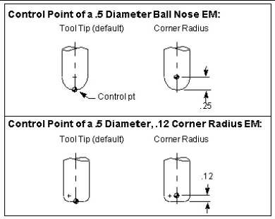
📝 NOTES:
-
If Corner Radius is used with non-ball nosed end mills, the offset is calculated along the tool axis, from the tool tip to the center of the first arc encountered in the tool profile. Corner Radius is only applicable to APT.
-
To specify a milling tool control point other than the tool tip or corner radius, define tools via the Tool Manager and specify a control point offset via the tool's Properties.
This feature is not applicable to turning tools. Instead, define tools via the Tool Manager and specify a control point offset via tool Properties.
Translucent — When toggled "on" (checked), visible cutters and holders are displayed in translucent mode. When toggled "off" visible cutters and Holders are displayed in solid mode.
| Translucent mode | Solid mode |
|---|---|
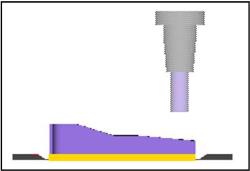 |
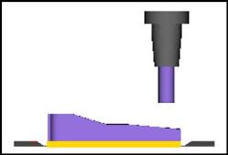 |
Configure NC Programs
Not to be confused with the similarly named Configure NC Program section which is a subbranch of this Configure menu.
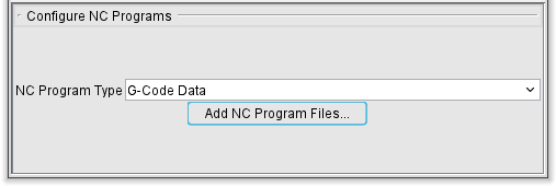
NC Program Type — Type of NC program file for Optimizer to simulate. By default, Optimizer simulates G-Code or "machine code data" NC programs destined for a 3-axis mill machine with a "Fanuc-like" control. Using this option, you can quickly configure Optimizer to simulate NC programs from all popular CAM systems.
Options:
G-Code Data — G-Code NC program file. With this choice, Optimizer uses a Machine file, Control file, and G-Code settings (ref. Project tab > Settings > G-Code Advanced Settings) to interpret codes present in the file.
Vericut APT — Generic ASCII APT NC program file from virtually any source, including ACL format.
UG CLS — UG CLS NC program file.
CATIA APT — CATIA APT source NC program file. This file must be processed from CATIA using the CATUTIL function and typically has a ".APTSOURCE" extension.
CV APT — ComputerVision APT NC program file.
CADRA APT — CADRA APT NC program file.
APT (RevPost) — ASCII APT NC program file created from reverse post-processing G-Code data.
Pro/MFG APT — Pro/Manufacturing APT NC program file.
NCL APT — NCL APT NC program file.
KRL — Displays the following Configure NC Programs menu:
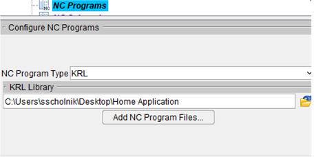
KRL Library — The location of the folder containing KRL library files for this project.
Add NC Program Files — Opens the NC Programs file selection window enabling you to add one or more NC program files to the list.
Configure NC Program
Not to be confused with the similarly named Configure NC Programs section which is the parent branch of this Configure menu.
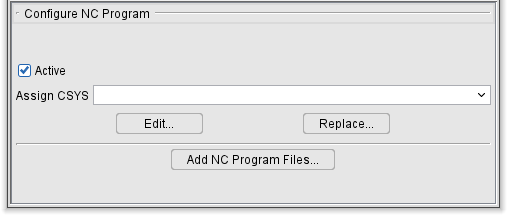
Active — When toggled “on” (checked), the highlighted NC program file is designated as “active”. When toggled “off”, the highlighted NC program file is designated as “inactive”. Only NC program files designated as “active” are processed by Optimizer. "Inactive" NC program files are indicated by red text in the Project Tree panel.
Assign CSYS — Use to assign a coordinate system (CSYS) to the highlighted NC program file. Select the desired CSYS from the pull-down list. Optimizer will append the selected CSYS to the NC program file in the Project Tree.
Edit — Opens the highlighted NC program in the NC Program Editor window.
Replace — Opens the NC Programs file selection window enabling you select one, or more NC programs to replace the NC program highlighted in the Project Tree.
Add NC Program Files — Opens the NC Programs file selection window enabling you to add one or more NC program files to the list.
Configure NC Subroutines
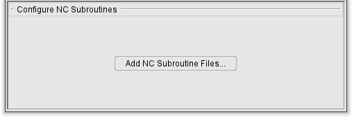
Add NC Subroutine Files — Opens the NC Subroutine file selection window enabling you to add one or more NC program files to the list.