CATIA V5-to-Vericut Interface (CATV5)
Prerequisites
CATV5 is a licensed software program that provides a CATIA V5 to Vericut data transfer connection. The interface is an executable that is designed to work with CATIA V5.
Versions supported:
CATIA V5 R18 (or later)
CGTech Licensing:
CATIA V5 Interface
Minimum Vericut Version required:
Vericut 8.0
Minimum Optimizer Version required:
1.1
Minimum Vericut License Version required:
9.4
Configuration
For the CATV5 Interface, no user configuration is required. The interface installation files are located at C:\Program Files\CGTech\Vericut x.x.x\windows64\catv5 and can be accessed directly from CATIA V5 or C:\Program Files\CGTech\Vericut x.x.x\windows64\commands\catv5.bat
Environment variables
To enable CATIA V5 to find the necessary Vericut files, you also need to define three environment variables, CGTECH_INSTALL, CGTECH_PRODUCTS and LSHOST. CGTECH_SINGLE_PLATFORM and CGTECH_CATV_LANGUAGE are optional.
| No. | Environment Variable | Example |
|---|---|---|
| 1 | CGTECH_INSTALL | C:\Program Files\CGTech\Vericut x.x.x |
| 2 | CGTECH_PRODUCTS | C:\Program Files\CGTech\Vericut x.x.x\windows64 |
| 3 | LSHOST | localhost |
| 4 | CGTECH_SINGLE_PLATFORM | YES |
| 5 | CGTECH_CATV_LANGUAGE | C:\Program Files\CGTech\Vericut x.x.x\windows64\catv5\CATVFrench.local |
| 6 | CGTECH_VO_INSTALL | YES |
CGTECH_INSTALL is set to the Vericut installation folder. In the above table, x.x.x represents the Vericut release number. For a typical Vericut 9.7 installation this variable is set to C:\Program Files\CGTech\Vericut 9.7. Defining a value explicitly for the CGTECH_INSTALL environment variable is optional. It can be derived from the CGTECH_PRODUCTS environment variable value.
CGTECH_PRODUCTS is set to the folder for the specific operating system of the computer running Vericut: "windows64". In the above table, x.x.x represents the Vericut release number. For a typical Vericut 9.7 installation this variable is set to C:\Program Files\CGTech\Vericut 9.7\windows64.
LSHOST is set to the name of the license server computer.
CGTECH_SINGLE_PLATFORM=YES If you are using Vericut single Platform then an additional environment variable needs to be defined for the interface.
CGTECH_CATV_LANGUAGE If you want the interface to use something other than US English, the variable can specify a file of localized text. Versions for French, German and Japanese are supplied.
CGTECH_VO_INSTALL — if set to “YES” (all CAPS) the Optimizer interface will start, otherwise it will be the Vericut interface.
📝 NOTE: One can also switch between the two using the radio buttons in the Options dialog.
Use the Microsoft Windows Control Panel > System Properties > Advanced tab > Environment Variables feature to define these environment variables. See Microsoft Windows Help for more information.
To add an icon to the Toolbar
If you wish to have an icon (
 ) on a CATIA V5 toolbar, the two icon files must be placed where CATIA V5 expects to find them. The paths depend on where you have CATIA V5 installed, but typically you will find a "small" and "normal" folder under "C: Program Files\Dassault Systemes\Bxx\win_b64\resources\graphic\icons". Place the two versions of the CATV5 icon, both called "I_CATV.bmp", in the appropriate folders.
Adding the CATV5 icon () to a CATIA V5 toolbar is a multi-step process;
-
Get CATIA V5 running.
-
Make the "Advanced Machining" workbench active, either by accessing an existing CATProcess file, or by initializing a new one. One or more of the Manufacturing toolbars are likely to be suitable locations for the CATV5 icon.
-
Pick "Tools" > "Macro" > "Macros" from CATIA V5's menus.
-
In the "Macros" dialog, pick "Macro Libraries".
-
In the "Macro Libraries" dialog, set the "Library Type" to "Directories".
-
Pick "Add existing library ..." and select the folder containing the CATV.CATScript file (for example "C:\Program Files\CGTech\Vericut x.x.x\Windows\catv5").
-
"Close" the "Macro Libraries" dialog.
-
"Close" the "Macros" dialog.
-
Pick "Tools" > "Customize ..." from CATIA V5's menus.
-
In the "Customize" dialog, bring the "Commands" tab to the front.
-
Select "Macros" from the left-hand list of "Categories".
-
Pick "CATV.CATScript" from the right-hand list of "Commands".
-
Click on the "Show Properties ..." button.
-
Pick the "..." button to the right of the "Icon:" label.
-
In the "Icon Browser" dialog you need to step through the pages of icons until you find the one for CATV5 (
). The icons are presented in alphabetic order of their names, which you can see by allowing the mouse cursor to sit over an icon for a brief period. The CATV5 icon () will probably be on the twelfth page. Pick it and "Close" the "Icon Browser". -
Back on the "Customize" dialog, position the mouse cursor over the name of the macro, CATV.CATScript, in the right-hand list, depress the left mouse button, and drag the cursor to the toolbar where you want the icon to appear. It's counter-intuitive, but you drag the macro name, not the icon! Repeat this step if you want the icon to appear on more than one toolbar.
-
"Close" the "Customize" dialog.
Microsoft Redistributables
The interface may require the Install of Windows C++ run-time libraries (Microsoft Redistributables). The Microsoft Redistributable vc_redist.x64.exe Installer is also available for download at: https://learn.microsoft.com/en-us/cpp/windows/latest-supported-vc-redist?view=msvc-170
Usage
The CATIA V5-to-Vericut Interface (CATV) exports the Catia manufacturing data to Vericut, CATV addresses the below Vericut setup requirements and then launches Vericut with the simulation ready to play.
The Vericut simulation requirements are:
-
Select a VMC (Vericut Machine Configuration)
-
Select and orient stock, fixture and design models
-
Select NC Programs & Subroutines
-
Define Cutting tools
-
Define Work Offsets Tables
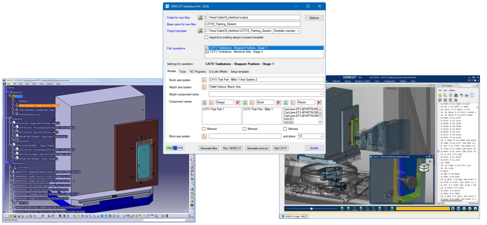
Accessing the CATIA V5-to-Vericut Interface
From the CatiaV5 Toolbar select the Vericut or Optimizer icon or execute the CATV5 batch file:
C:\Program Files\CGTech\Vericut x.x.x\windows64\commands*catv5.bat*
📝 NOTE: CATV5** requires an active NC Manufacturing file running in order to interface with Vericut.
User Interface & Operation
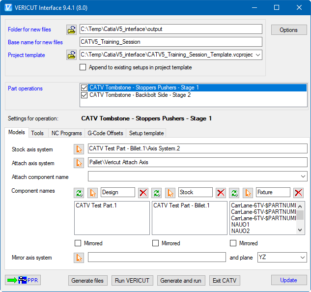
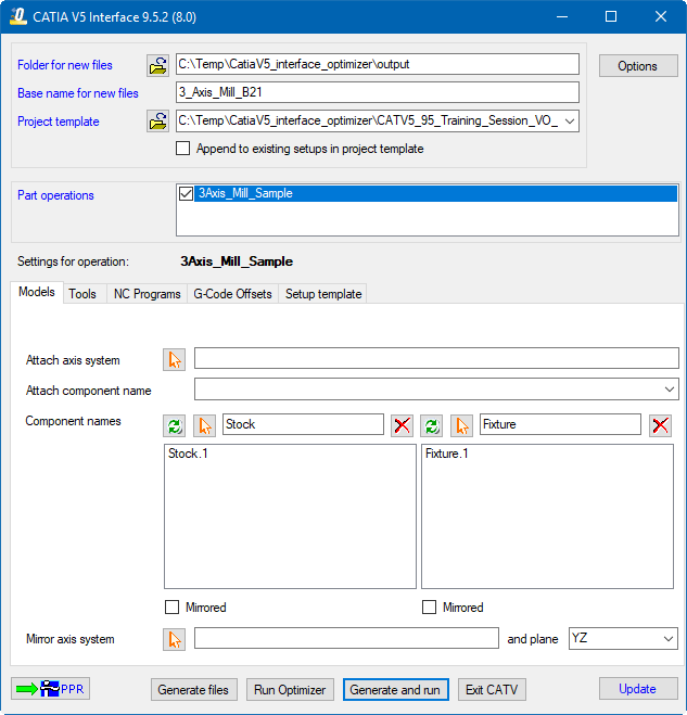
When you trigger CATV5, either with the toolbar icon or from with catv5.bat, you should see a window similar to this.
Vericut:
Optimizer:
📝 NOTE: The Interface Checks Out a license when the Interface is opened and then the Interface Checks In the license when the Interface is closed.
📝 NOTE: The fields in Black are Part Operation specific while the Blue fields are common to all Part Operations

CATIA V5 can have more than one CATProcess file open at once. CATV5 is not aware when you switch between files in CATIA V5. This button forces the program to refresh the interface content from the currently active CATProcess file. If the active CATIA V5 file is not a CATProcess (it could be a CATPart for example) the program will display a warning message.
Files

CATV5 will generate several files to pass CATIA V5 information to Vericut. For verification or simulation of one CATProcess file, the following can be created;
• Several temporary files (with the ".VcTmp" extension)
• tool libraries (with the ".tls" extension)
• model files (STL format)
• NC programs (in APT or G-Code)
All these files will be placed in a single folder. If you have defined the CGTECH_CATV_FOLDER environment variable, the folder it references will appear in the upper text field of this pair. If not, the location of the CATProcess file will be presented so that you can keep all the related files in one place. In either case you can override the suggested folder, by entering a different location, or by browsing ( ) for one.
The names of created tool libraries, model files and NC programs depend on the names of the corresponding CATIA V5 objects (CATParts, and Part Operations). But the temporary files, the final Vericut project, and its log file are given the same name, which is provided by the lower text field of this pair. By default it will be filled in with the CATProcess name, but you can override it if you wish.
Project Template

The files generated by CATV5 are intended to be "add-ons" for existing Vericut projects that contain much more detail than is present in a CATProcess file. For example, you may have a machine and control fully specified in a project file, and simply wish to place the CATProcess stock and fixtures on this machine before verifying the new NC programs. In this field you can specify a template file for the project. Normally such a file has the extension ".VcProject". Note that you can also specify a different template for each CATIA V5 part operation (called a "Setup" in Vericut). If you do not specify a project template, either "init.VcProject" or "initm.VcProject" will be used, depending on whether CATIA V5 has the unit of length set to "inch" or "millimeter".
If you wish to append the part operations from a CATProcess file to the setups that are already defined in your project template, you can click on the check-box under the template field. Otherwise, and more typically, the imported part operations will be the only setups in the generated project.
Part Operations

This list contains the names of all the part operations found in the CATProcess file. Typically, you would leave each setup "checked" so that they will all be simulated, but you could cause any of them to be skipped by unchecking their names. When you select a setup name, most of the other elements of the interface will change to reflect the choices made for that setup. Items with blue labels are "project wide" and do not change.
Models tab
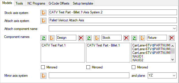
Vericut:
Optimizer:
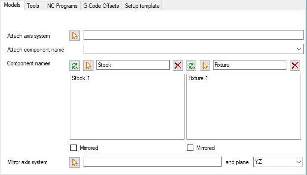
Stock Axis System

CATProcess files with multiple part operations seem to exhibit two different operator styles. In the first style, the stock is represented just once and each setup contains a different set of fixtures, some of which will typically be instances of the same CATProduct or CATPart. The second style may or may not use a common set of fixtures, but will have multiple instances of the stock, probably in different orientations and locations. In Vericut, we need to know what happens to the stock between setups.
You need to pick an axis system in each setup which has the same relationship to the stock. Thus if the stock needs to be flipped over between setup one and two, you would pick an axis system for both, but two of the axes will probably be reversed in the second one. Typically the same axis system in the two instances of the stock model is adequate. To graphically select an axis system, click on the  button, then pick a machining axis system or an axis system on a part. To exit selection mode without making a choice, use CATIA V5's "Edit" > "Undo" option.
Note that you can reverse the selection sequence by picking an axis system first, then clicking the button. The name of the selected axis system will appear in the field.
Attach Axis System

If the first of these two fields is left blank the setup's machining axis system will be placed on one of the Vericut machine's "attach" components. Note that a setup's machining axis system is the last such system encountered in CATIA V5's process tree before the setup's first active tool change. This is not always the axis system of the CATIA V5 machine. If the setup's machining axis system does not coincide with one of the Vericut "attach" components, you can pick a different axis system for the setup.
To graphically select an Attach axis system, click on the button, then pick a machining axis system or an axis system on a part. To exit selection mode without making a choice, use CATIA V5's "Edit" > "Undo" option.
Note that you can reverse the selection sequence by picking an axis system first, then clicking the button. The name of the selected axis system will appear in the first of these two fields.
In the second field you can specify the name of the corresponding Attach component. If left blank, the default name "Attach" will be used.
Models
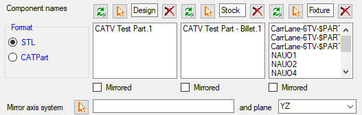
For each setup you should specify the names of the components in Vericut in which the design, stock and fixture models will be placed. Default component names are simply "Design", "Stock" and "Fixture" or their localized equivalents.
You also need to specify which of the CATParts represent the design, the stock and the fixtures. Normally it is only necessary to have a stock model for the first setup, as it will get passed to subsequent ones in Vericut. Likewise, you will probably only nominate a design model in the last setup, to be used with AUTODIFF. But fixturing will often be different in each setup. If design, stock or fixture models have been specified in CATIA V5 for its video "simulation" capability, you can use the corresponding  button to wipe out any parts currently in the displayed list, and replace them with the parts used for CATIA V5's video.
Otherwise you can graphically select design, stock or fixture models, by clicking on the corresponding button. Then you can pick a product from any level in CATIA V5's product list tree, or from the picture of the models. Note that the product must be within the major branch of the tree that is referenced by the setup's part operation. All instance names of all CATParts under the selected product in the tree will be placed in CATV5's list for this setup. To exit selection mode without making a choice, use CATIA V5's "Edit" > "Undo" option. Note that you can reverse the selection sequence by picking a product first, then clicking the button.
If you decide that you don't want all the detailed parts, such as bolts, transferred to Vericut, you can remove names from any of the three lists by selecting them and clicking on the appropriate  button. The "Shift" and "Ctrl" keys can be used in the normal way to select multiple names from the list so they can be removed together.
Each set of models, for the design, stock or fixtures can be individually mirrored through one of the three orthogonal planes defined by a selected coordinate system.
Tools tab
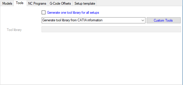
Typically you would have CATV5 generate tool libraries (with the ".tls" extension) from the tool data in the CATProcess file for each setup. If desired, you can request that all tools for all setups be placed in a single library. You can also elect, on a setup by setup basis, to merge the generated tools into the library which is referenced by your setup (or project) template file, to use that referenced library "as is", use an existing tool library by selecting it, or use a tool list from a TDM database by specifying its name.
Using any of these last three options implies that you are sure that the tool geometry present in the CATProcess file is accurately represented in the referenced library, selected library or specified TDM list.

Within the CATProcess file you can define the cutting geometry of a wide variety of tool types, and for milling tools define their holders as a stack of up to five cylinders and cones. If this is not adequate, you can define a milling tool's cutter and holder with a CATPart or CATProduct.
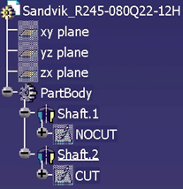
A CATPart would contain two sketches, with names \"CUT\" and \"NOCUT\" to define the half cross-section which is rotated around the tool\'s axis. Typically, the part can have shafts defined by the rotated sketches, but this is not essential.
A CATProduct can reference multiple CATParts, each with a named attribute, "CuttingType". Values of these attributes can be \"CUTTER\", \"SHANK\" or \"HOLDER\" and each CATPart should contain a sketch to define the half cross-section which is rotated around the tool's axis. Shafts can be defined by the rotated sketches, but this is not a requirement.
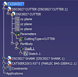
To make CATV5 aware of these custom milling tool profiles, click on the "Custom Tools" button, which is blue to reflect the fact that the connections that you make between tool names and CATParts or CATProducts will be "project wide". If the same tool is used in more than one setup, it is only necessary to specify once the CATPart or CATProduct containing its sketches. When you click on the blue button, another dialog is displayed.
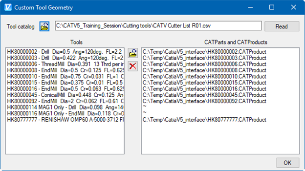
If your site uses one or more CATIA V5 tool catalogs, which most likely started life as Excel spreadsheets, and you have the ".csv" versions of those catalogs, then you can use them to populate the two lists in the "Custom Tool Geometry" dialog shown below.
Use the upper button to browse for a ".csv" catalog. When you click on the "Read" button, the catalog is scanned for any of the tool identifiers in the left-hand list. When a tool is found, the reference to the CATPart or CATProduct that defines the tool geometry is copied from the tool's catalog entry to the right-hand list. You can repeat this process for each relevant catalog, assuming that if a tool appears in more than one catalog then its referenced CATPart or CATProduct will be the same in each.
To individually make the connection between a tool and its CATPart or CATProduct, select the tool's name in the list on the left, then click on the button between the two lists. You will be offered the usual file selection dialog to pick a CATPart or CATProduct, and the file's name will then be displayed in the list on the right.
Repeat this sequence for all the tools that have corresponding CATParts or CATProducts. If you wish to break a connection, and revert to using the CATProcess file's definition of a tool's geometry, you can select the tool in the list and click on the  button. When you have all the pairings established, click on the "OK" button and the dialog will disappear.
NC Programs tab
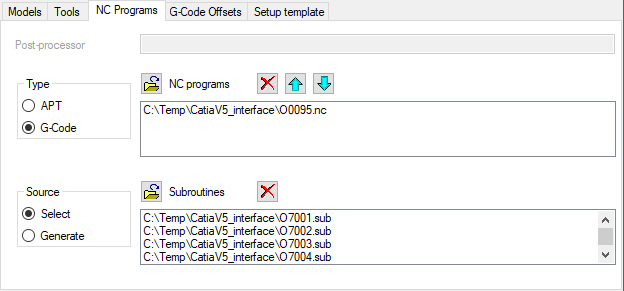
Post-Processor

This field will only be enabled when you elect to generate G-Code programs. It should specify the post-processor to be used to convert APT to G-Code. Posts from three vendors are supported by CATIA V5; Cenit, IMS and ICAM. Their location is dependent on where CATIA V5 was installed, but will typically be in folders under "C:\Program Files\Dassault Systemes\Bxx\intel_a\startup\Manufacturing". Cenit posts have the extension ".pp", IMS uses ".lib" and ICAM's have ".dmp". You can paste a post's full path and name into this field, or browse () for it.
Type
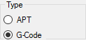
Specify here whether the NC programs to be passed to Vericut are APT or G-Code. APT programs can be generated more quickly, since the post-processing step is not required, and are fine for initial program verification. G-Code is one of the prerequisites for machine simulation.
Determination of the fast feedrate, which will be set in the Vericut project file, is dependent on this choice. For APT programs, the first 5000 lines of the first program are scanned, and the fastest of the encountered feedrates is used, with the addition of a small increment (0.05 when the linear unit is "inch", 1.0 when it is "millimeter"). For G-Code programs, all the active machines in the CATProcess file are scanned, and the largest of their maximum fast feedrates is used.
Source
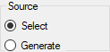
CATV5 can cause CATIA V5 to generate the NC programs defined in the CATProcess file. Alternatively you can choose to select NC programs that have already been created. G-Code programs produced by a post that is not accessible within CATIA V5 would be a good example.
NC Programs
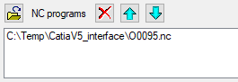
If you choose to have CATV5 and CATIA V5 generate the NC programs, they will be listed here as they are created. Alternatively, you can browse () for existing programs. If you do so, it is important to ensure that the list is in the order of cutting. You can erase () programs from the list, or re-arrange them ( or
or  ).
).
Subroutines
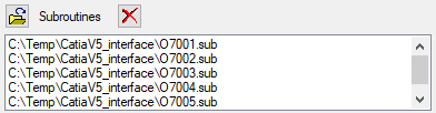
If you have G-Code programs that reference subroutines, you can browse () to select the existing subroutine files. You can also erase () subroutines from the list.
G-Code Offsets tab
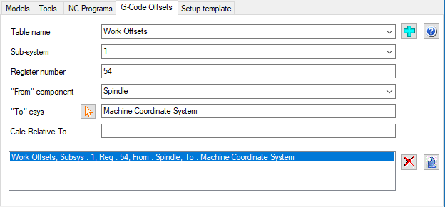
For each CATIA V5 part operation, the machining axis system defines the origin of the coordinates in the NC programs. Typically, this origin will be used to define the content of the "Program Zero" table in Vericut. But there are other tables that you could use to locate the NC programs relative to the machine axes. For example, you may wish to use a "Work Offsets" table for register 54. And you could associate the machining axis system to a different component of the machine, such as a head or turret. In the first of the four boxes in this dialog, you can enter the required parameters. There are four choices of table name in the drop-down list, but you can enter a different name if necessary. If you click on the  button, the list of table names will be populated by scanning the template for the setup or project. The first table encountered that has an associated sub-system, register number and "from" component will become the selected one. Use the
  Add icon to add a table. Make the appropriate selections and press the "Add". Use the
  Modify icon to modify an existing table. Select the table in the current list, make the appropriate changes and press the "Modify". Use the () Remove icon to remove a table. Select it in the list and press the "Remove".
Select the desired table name from the Table List pull-down list. The Table List pull-down list contains the following Vericut G-Code tables: Program Zero, Work Offsets, and Base Work Offset. The Subsystem is used to specify the machine subsystem ID for which the table is being defined. Select the subsystem ID from the pull-down list. Register is used to specify the table register number, example; for a G54 enter 54.
The From component pull-down list is used to select the name of the component that represents the "from" point for determining the program zero offset. The To Csys, by default, Machine Coordinate System is set, use the select button and pick the name of a CSYS to represent the "to" point for determining the program zero offset. Use the Calc Relative to feature to set a relational offset recalculated in the machine position where the offset will be used. The new position is immediately calculated and stored and therefore is not dependent on the machine position when the offset is activated.
Setup Template tab
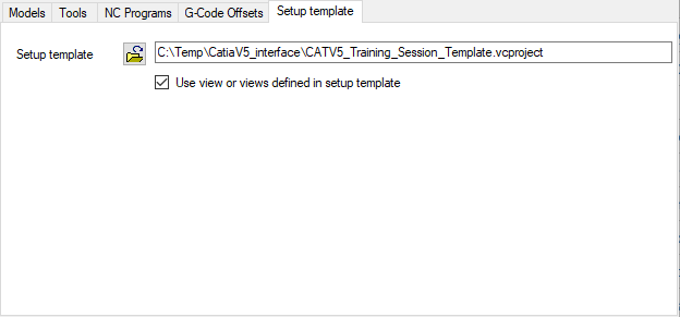
If all part operations in the CATProcess use the same machine, and that machine is defined in the project template file, you could leave the setup template field blank. If there are several machines involved, you will need to have a Vericut project file for each one, and will specify which file each setup should use in this field.
CATV5 can generate a single Vericut view for each setup, with the stock in the same orientation as it appears in CATIA V5. Alternatively, if you wish to use the view (or views) already established in the setup (or project) template file, you can click on the check-box.
Options button
Application tab
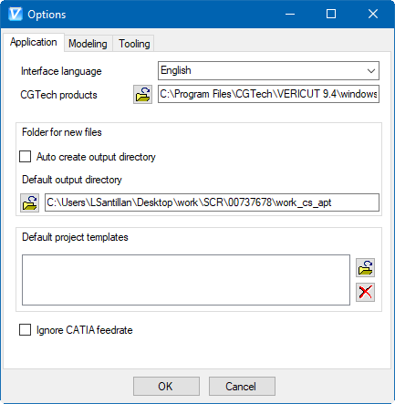
User can change the language of the interface here, runtime, by selecting any of the language on the drop-down menu provided. User can edit/specify here the path for ‘commands’ folder which contains the Vericut batch file, inside Vericut installation directory. Use the CGTech products browse ( ) button to display a file selection window and use it to select the ‘commands’ folder.
User can choose to have interface 'auto create' output directory so that user does not have to provide one explicitly. This is possible by checking 'Auto Create Output Directory' check-box. In this case, every time user opens interface, a directory named 'output' will be created (if does not already exist) underneath the main directory in which corresponding Catia project is located. This newly created 'output' directory will be chosen as an interface output directory and will be displayed to the user. Un-checking 'Auto Create Output Directory' checkbox enables 'Default Output Directory' text box and button which otherwise are disabled. If user wants to output all interface exported files to one default folder, it is possible by providing path to the 'Default Output Directory' text box. User can also locate path using the Browse () button. User defined path here will be chosen as interface output directory and displayed on the interface in all future interface sessions.
List of Vericut project file that can be used as project templates can be specified here. Files listed here will be displayed in 'Project Directory' pull-down list on the main interface window. Use the browse () button to display a file selection window and use it to display a file selection window and use it to select the required Project Template. Use to delete () button to delete the highlighted Project Template from the List.
The Ignore CATIA feedrate is checked if the user does not want to override the maximum feed rate specified in the project or setup template.
Modeling tab
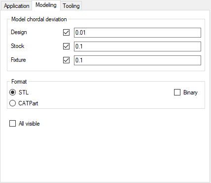
Model chordial deviation
By default the precision of the created STL files is controlled by settings within CATIA V5, and will be the same for all design, stock and fixture models. Alternatively, you can specify a different chordal deviation for any or all of the three types of model, by "checking" types and providing maximum deviation distances. These options pertain to all setups.
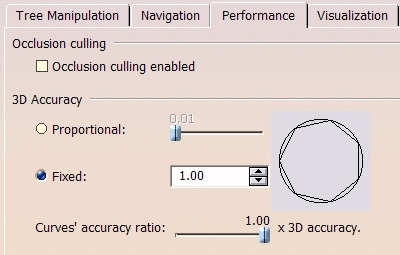
For each "checked" model type, when an STL file is generated, the chordal deviation value provided is temporarily inserted into CATIA V5's "Tools > Options > Display > Performance > 3D Accuracy > Fixed" field, and the "Fixed" option is selected. For each "unchecked" model type, the user's settings for "3D Accuracy" apply. CGTech's staff does not pretend to understand CATIA V5's physical interpretation of the "Fixed" accuracy value, which appears to be non-dimensional and is limited to lie between 0.01 and 10.
Format
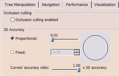
Vericut can accept part models in a variety of formats, including STL and native CATPart files. You can adjust the precision of STL model types by performing the following procedure in CATIA V5. This only needs to be done once.
-
Pick "Tools" > "Options ..." from the CATIA V5 menus.
-
In the "Options" dialog, expand the "General" branch of the tree.
-
Pick the "Display" sub-branch.
-
Bring the "Performance" tab to the front.
-
Under "3D Accuracy" pick "Proportional", and move the corresponding slider to the extreme left. The displayed value will then be "0.01".
-
Click on the "OK" button.
Using CATParts is the fastest choice for CATV5 because the files are simply referenced, but there is a performance penalty when Vericut has to first access these files. Because some models may be used in several setups, this is a "project wide" parameter, so that we avoid having more than one version of the same model.
Check Binary if the user wishes to generate binary STL files instead of ASCII STL files. The All visable setting is checked used if the user wishes to ignore hidden state of models in the CATProcess set.
Tooling tab
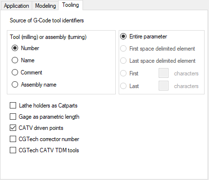
When CATIA V5 uses a post to generate the NC programs, the tool identifiers within the G-Code can be extracted from several of the tool or assembly's parameters. Typically, the tool number (for a milling tool) or the assembly number (for a turning tool) are used. But a post could access names or comment fields too. In the second of the three boxes you can select which field contains the tool identifiers, and in the lowest box you can specify how identifiers are to be extracted from the chosen field.
The "Defaults" button can be used to revert to CATIA V5's model file precision, the "Program Zero" table and using the entire number field as the source of tool identifiers.
Press the "OK" button when you have defined the model file precision, table parameters and/or the source of the G-Code tool identifiers, and the extra "Options" dialog will disappear.
PPR button

If you set many of the parameters above but then decide that you are not ready to transfer the data to Vericut, you can click on this button to save all the project and setup parameters in the active PPR document. You would still need to save that document as a ".CATProcess" file to preserve your work.
CATV stores data as Parameters within Catia. To access these Parameters, make the Process active in the tree, then select Formula and then set Filter Name equal to "cgt".
Output buttons

When you have provided CATV5 with all the information it needs, you can perform the transfer of data to, and triggering of, Vericut.
Click on the "Generate files" button to create the tool libraries, models and NC programs without triggering Vericut. Once you have all the files needed, you can fire up Vericut with the "Run Vericut" button.
You can perform both of these steps at once with the "Generate and run" button. Data transfer, particularly if you are generating and post-processing large NC programs, can be time consuming, so a dialog is presented which provides a simple indication of progress. The "Exit CATV5" button terminates the program.
Usage Variables
The following optional environment variables are available for use with the CATIA V5 Interface.
| No. | Environment Variable | Example |
|---|---|---|
| 1 | CGTECH_CATV_FOLDER | C:\Temp |
| 2 | CGTECH_GCODE_EXTENSION | mcd |
| 3 | CGTECH_CATV_LATHE_HOLDER_PARENT_FOLDER | path to Vericut tools parent folder |
CGTECH_CATV_FOLDER set if the user wishes to have all files generated by CATV5 placed in a single nominated folder.
CGTECH_GCODE_EXTENSION set if the user wishes the file extension ".mcd" to be used for the extension on all posted g-code files when post processing via CATV5.
CGTECH_CATV_LATHE_HOLDER_PARENT_FOLDER set folder which has a sub-folder per turning tool assembly, with the holders' CATParts in these sub-folders
Preferences
Preferences File
Also known as ‘prefs’ file, stores all user specified ‘global’ settings for interface operation. The settings stored are called ‘global’ because they are responsible for overall look & feel and operational behavior of the interface. They are not tied to any specific CATIA V5 project. By default, ‘Preferences’ file is generated at C:\Users\username\catv5_user.prefs.
"Quick Start" training session
The CATIA V5-to-Vericut Interface “Quick Start” training session is designed to quickly teach a Vericut user the “basics” of using the CATIA V5 Interface. The download includes: CAD/CAM files, Vericut files, and step-by-step training sessions in PDF format.
Download: https://vericut.com/products/vericut-interfaces
📝 NOTE: to run the Quick Start files, CATIA V5 R21 or later is required