GibbsCAM-to-Vericut Interface (GibbsV)
Prerequisites
GibbsV is a licensed software program that provides a GibbsCAM to Vericut data transfer connection. The interface is an executable that is designed to work with GibbsCAM.
Minimum Version supported:
GibbsCAM 2024
CGTech Licensing:
GibbsCAM Interface
Minimum Optimizer Version required:
1.0
Minimum Vericut License Version required:
9.5
Configuration
To install the GibbsCAM-to-Vericut/Optimizer interface (GibbsV), download and run the gibbscam_interface_install.exe installer. Follow the step-by-step prompts to complete the setup.
You can download the installer from the Vericut website: https://vericut.com/previous-vericut-release
Manual installation
If you prefer not to use the installer, you can manually set up the GibbsCAM-to-Vericut/Optimizer interface (GibbsV). The interface consists of the following two files:
Installation Steps for the GibbsCAM Interface
The interface is distributed as 7 files:
GibbsV.dll — the core interface library
Gibbsv[language].local — localization file for your preferred language
Steps:
- Copy from:
For Vericut - C:\Program Files\CGTech\Vericut x.x.x\windows64\GibbsV\version\GibbsV.dll
For Optimizer - C:\Program Files\CGTech\Optimizer\windows\64GibbsV\version\GibbsV.dll
- Copy to the appropriate location based on your GibbsCAM version:
GibbsCAM 2026 and later
C:\Program Files\Gibbs\GibbsCAM\version\PlugIns\GibbsV.dll
GibbsCAM 14.0.37 to GibbsCAM 2025
C:\Program Files\CAMBRIO\GibbsCAM\version\PlugIns\GibbsV.dll
GibbsCAM 2014 to GibbsCAM 14.0.11
C:\Program Files\3D Systems\GibbsCAM\version\PlugIns\GibbsV.dll
Environment variables
To enable GibbsCam to find the necessary Vericut files, you also need to define three environment variables, CGTECH_INSTALL, CGTECH_PRODUCTS and LSHOST. CGTECH_SINGLE_PLATFORM and GIBBSV_LANGUAGE are optional.
| No. | Environment Variable | Example |
|---|---|---|
| 1 | CGTECH_INSTALL | C:\Program Files\CGTech\Vericut x.x.x |
| 2 | CGTECH_PRODUCTS | C:\Program Files\CGTech\Vericut x.x.x\windows64 |
| 3 | LSHOST | localhost |
| 4 | CGTECH_SINGLE_PLATFORM | YES |
| 5 | GIBBSV_LANGUAGE | C:\Program Files\CGTech\Vericut x.x.x\windows64\GibbsV\version\GibbsvJapanese.local |
| 6 | CGTECH_VO_INSTALL | YES |
| 7 | CGTECH_GIBBSV_DEBUG | 1 |
| 8 | CGTECH_GIBBSV_NEW_TLS | 0 |
| 9 | GIBBSV_USE_TOOL_NUM | YES |
CGTECH_INSTALL is set to the Vericut installation folder. In the above table, x.x.x represents the Vericut release number. For a typical Vericut 9.7 installation this variable is set to C:\Program Files\CGTech\Vericut 9.7. Defining a value explicitly for the CGTECH_INSTALL environment variable is optional. It can be derived from the CGTECH_PRODUCTS environment variable value.
CGTECH_PRODUCTS is set to the folder for the specific operating system of the computer running Vericut: "windows64". In the above table, x.x.x represents the Vericut release number. For a typical Vericut 9.7 installation this variable is set to C:\Program Files\CGTech\Vericut 9.7\windows64.
LSHOST is set to the name of the license server computer.
CGTECH_SINGLE_PLATFORM=YES If you are using Vericut single Platform then an additional environment variable needs to be defined for the interface.
GIBBSV_LANGUAGE If you want the interface to use something other than US English, the variable can specify a file of localized text. Versions for French, German, Italian, Chinese, and Japanese are supplied.
If the GIBBSV_LANGUAGE environment variable is set, then it will use that as the default language. If the user interactively changes the language in the GUI, then the newly selected language file is searched for in the same directory defined in the GIBBSV_LANGUAGE environment variable. If the GIBBSV_LANGUAGE is not defined, then the language file is searched for in the "GibbsV" subdirectory under the install directory.
CGTECH_VO_INSTALL — if set to “yes” the Optimizer interface will start, otherwise it will be the Vericut interface. Note: One can also switch between the two using the radio buttons in the Options dialog.
CGTECH_GIBBSV_DEBUG — Purpose: Use this variable to display the debug Matrix window. This window is used to show the matrices associated with all Coordinate Systems present in the GibbsCAM file. Once OK is selected to all, then the Interface will launch Vericut. Note: The debug Matrix window will only display if the Output All Coordinate Systems check-box is checked.
CGTECH_GIBBSV_NEW_TLS — Purpose: By default the GibbsCAM Interface exports Tool Manager 9.5 version files. To activate the old tooling logic, set CGTECH_GIBBSV_NEW_TLS to 0. If this environment variable is set to 0, then the Interface exports Tool Manager 7.3 version files.
CGTECH_GIBBSV_NEW_TLS — Purpose: If GIBBSV_USE_TOOL_NUM=NO or not defined, then CGV will create tool ID's based on the "TGx_y" format and creates a tool list. This is the default behavior. If GIBBSV_USE_TOOL_NUM is set to YES, then CGV will create tool ID's based on the tool number and not create a tool list.
To add an icon to the Toolbar
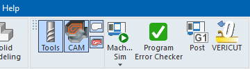
If you wish to add the Vericut ( ) or Optimizer (
 ) icon to the GibbsCAM toolbar…
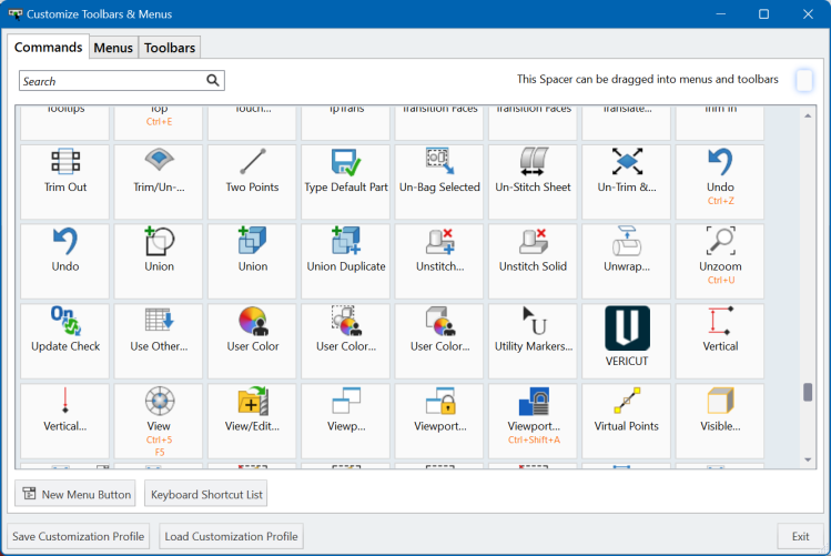
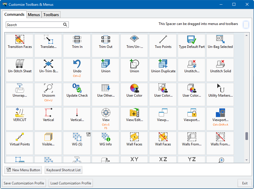
• From the GibbsCAM Toolbar, right click and select Customize Toolbar & Menus
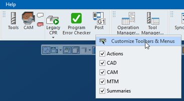
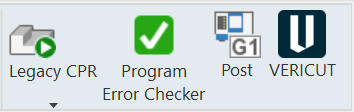
• Select the Vericut command, then drag and drop it onto the GibbsCAM Toolbar. The icon will appear differently in GibbsCAM depending on the setting of variable CGTECH_VO_INSTALL. If variable is set to YES () but if set to NO or not present ().
Vericut:
Optimizer:
• Close the Customize Toolbar & Menus window
Microsoft Redistributables
The GibbsCAM-to-Vericut Interface (GibbsV) may require the installation of Microsoft Redistributables, specifically the Windows C++ run-time libraries. These libraries ensure compatibility and proper functioning of the interface, allowing seamless data transfer between GibbsCAM and Vericut or Optimizer for manufacturing simulation.
📝 NOTE: A runtime library is a collection of low-level compiler support routines and functions that are used by virtually all programs compiled with GCC (GNU Compiler Collection) and can be downloaded here.
Usage
The GibbsCAM interface exports manufacturing data from GibbsCAM to Vericut/Optimizer, ensuring a seamless transition for simulation/optimization. It automatically configures the necessary Vericut/Optimizer setup requirements and launches the software, ready to process.
The following steps must be completed to run the interface:
-
Select a VMC (Vericut Machine Configuration) — Define the machine setup for simulation.
-
Select and orient stock, fixture and design models — Ensure correct positioning of components.
-
Select NC Programs & Subroutines — Load the necessary machining programs.
-
Define Cutting tools — Specify the tools used in the machining process.
-
Define Work Offsets Tables — Configure coordinate systems for accurate machining.
Accessing the GibbsCAM-to-Vericut Interface
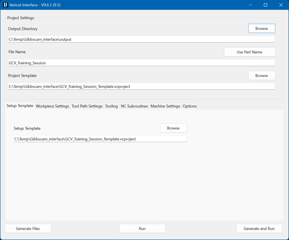
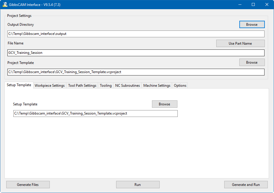
From the GibbsCAM Toolbar select the Vericut ( ) or Optimizer () icon or select menus Plugins > Vericut/Optimizer
📝 NOTE: GibbsV** requires an active NC Manufacturing file running in order to interface with Vericut.
Optimizer:
📝 NOTE: The Interface Checks Out a license when the Interface is opened and then the Interface Checks In the license when the Interface is closed
Project Settings
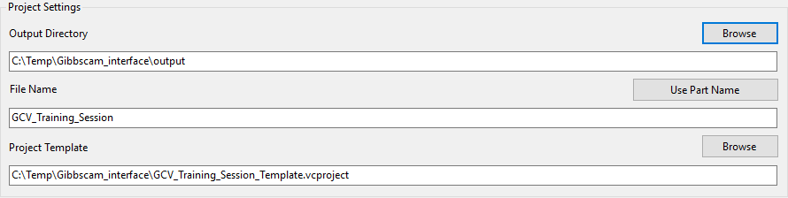
GibbsV will generate several files to pass GibbsCAM information to Vericut. For verification or simulation of one GibbsCAM part file, the following can be created;
• Vericut template file (*.VcTmp)
• Vericut Tool libraries (*.tls)
• Vericut Operation file (*.ops)
• Model files (*.stl and *.ply)
The Output Directory specifies the directory where you want the Vericut files to be written (.VcTemp, .tls, .ops, .ply, .stl). Type the Output Directory, or use the "Browse" button to display a file selection window to select the path. The File Name specifies the "base" name for all Vericut files that will be created. Type the File Name, or use the “Use Part Name” button to auto-fill the GibbsCAM part name.
The files generated by GibbsV are intended to be "add-ons" for existing Vericut projects that contain much more detail than is present in a GibbsCAM part file. For example, you may have a machine and control fully specified in a project file, and simply wish to place the GibbsCAM part stock and fixtures on this machine before verifying the new NC programs. In this field you can specify the Project Template file. Type the Project Template, or use the "Browse" button to display a file selection window to select the Vericut project template.
Setup Template
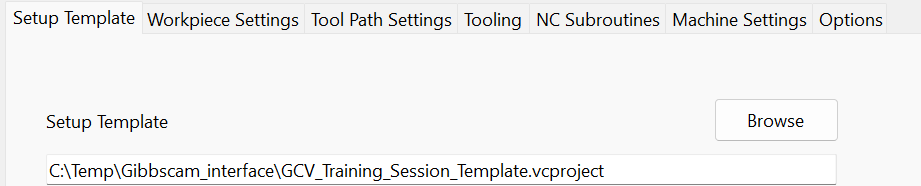
If all GibbsCAM part information use the same machine, and that machine is defined in the project template file, then the setup template field can be left blank. If there are several machines involved, you will need to have a Vericut/Optimizer project file for each one, and will specify which file each setup should use in this field.
Workpiece Settings tab
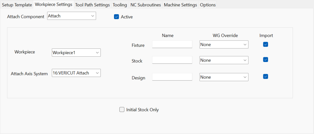
The attach components are read from the machine file that is specified in the project template (or from the machine file specified in the setup template if defined) and presented in a pull-down list called Attach Component. All attach components are active by default. The user can prohibit an attach component from being processed by unchecking the active check box.
For each attach component, a workpiece, an attach axis system, component names and work groups can be specified.
The Workpiece is the GibbsCAM part that is associated with the Vericut Attach Component.
The Attach Axis System is the GibbsCAM coordinate system that is associated with the Vericut/Optimizer Attach Component.
📝 NOTE: The Attach Axis System needs to be a GibbsCAM coordinate system which is a duplicate of the coordinate system XY Plane. This can be set with the Coordinate System Palette.
By default, the fixture, stock and design components will be named “Fixture,” “Stock,” and “Design” in Vericut. These defaults can be overridden by specifying a fixture, stock or design Name.
The fixture, stock and design WG Override specifies the work group geometry to be used for the fixture, stock and design model respectively instead of the default definition.
If you wish to transfer only the initial stock and the fixture and design models associated with it and ignore all other models, then you can click on the Initial Stock Only check-box.
The fixture, stock and design Import toggles allows the user to import or not import models for a corresponding component.
Model Type Assignment Logic
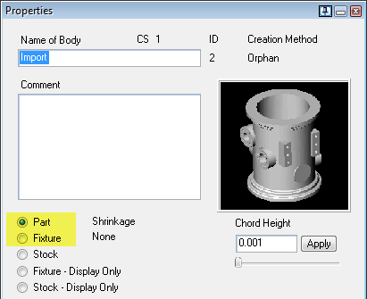
Fixture and Design Models: If the WG Override field is not defined, GCV will first reference the Properties window to determine the model type.
Stock Models: If the WG Override field is not defined, GCV will first reference the Properties window to determine the model type.
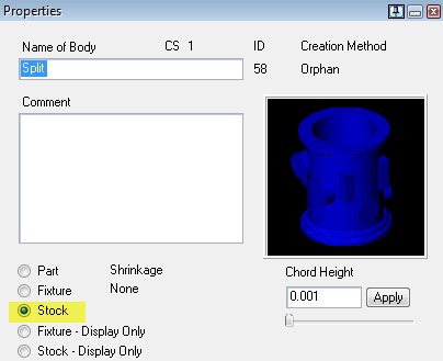
If the model type is not found in the Properties window, GCV will then check the Document Control dialog.
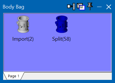
Body Bag handeling: Models placed in the Body Bag will be excluded from output. This function is used to remove unwanted or inactive models from the export process.
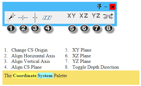
Attach Axis System Requirements
The Attach Axis System must be a GibbsCAM coordinate system that mirrors the XY Plane. You can define this using the Coordinate System Palette.
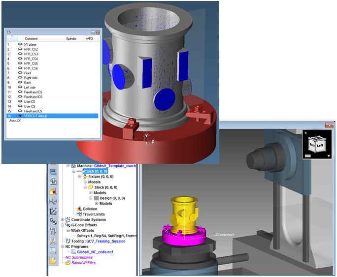
In GibbsCAM, the Vericut Attach coordinate system is automatically aligned with the position of the Vericut Attach component.
Tool Path Settings tab
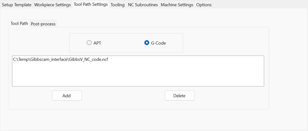
Specify whether the NC programs to be passed to Vericut are APT or G-Code. Use the “Add” button to browse for and add a tool path to the list. Use the “Delete” button to delete a tool path from the list. It is important to ensure that the list is in the order of cutting.
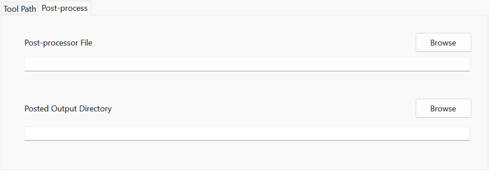
Use the Post-process feature to create new .ncf files from the GibbsCAM part file. Designate an optional output directory for posted G code files.
📝 NOTE: Preference file includes the "*.post" to GibbsVPostFilter tag as part of the default setting.
Tooling Tab
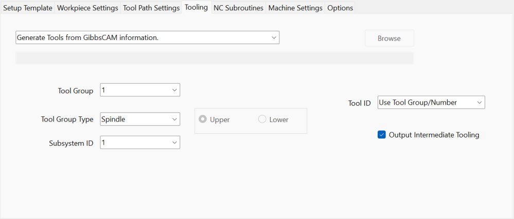
Select tool library information:
• Select Generate Tools from GibbsCAM information if you want Vericut to use the tool library file created by GibbsV.
• Select Use Selected Tool Library if you want Vericut to use an existing tool library file
• Select Use Tools from the Setup Template if you want Vericut to use the tool library file stored in the Setup Template rather than one created by GibbsV.
• Select Merge Tools into Setup Template Tool Library if you want Vericut to merge the tool library created by GibbsV, with the tool library file stored in the Setup Template, and use the "merged" tool library rather than one created by GibbsV.
For each Tool Group, you can specify the tool group type of Spindle, Turret, or Gang Tool, and you can specify the Subsystem ID. If Turret is selected, then you can select if Upper or Lower turret.
Select Tool ID information:
• Select Use Tool Group/Number if you want the tool ID to contain the tool group and tool number.
• Select Use Tool Number if you want the tool ID to contain the tool number only. A tool list will not be generated if this option is selected.
• Select Use Tool Comment if you want the tool ID to contain the tool comment only.
📝 NOTE: GibbsV will use the first quoted string from the GibbsCAM Tool Comments as the Vericut Tool ID and set the Vericut Tool Change By feature to Tool Number.
Output Intermediate Tooling: If checked, then intermediate tooling will be output with the tool if it exist, else no intermediate tooling will be output with the tool.
Environment variable called GIBBSV_USE_TOOL_NUM:
If GIBBSV_USE_TOOL_NUM=NO or not defined, then CGV will create tool ID's based on the "TGx_y" format and creates a tool list. This is the default behavior. If GIBBSV_USE_TOOL_NUM=YES, then CGV will create tool ID's based on the tool number and not create a tool list.
NC Subroutines tab
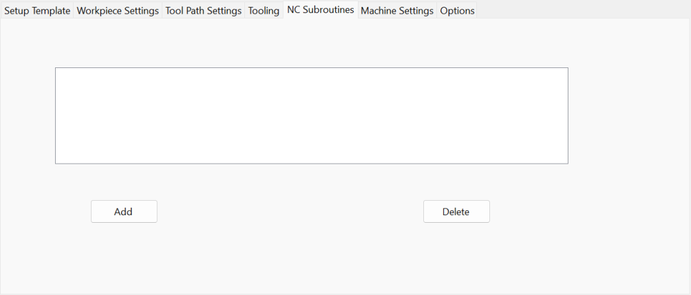
If you have G-Code programs that reference subroutines, you can use the “Add” button to browse for and add subroutine files to the list. Use the “Delete” button to delete subroutine files from the list.
Machine Settings tab
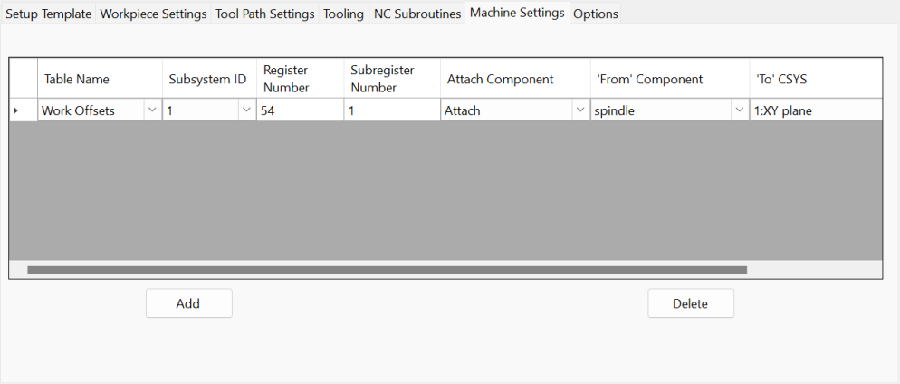
The Machine Settings list allows for the definition of work offsets which defines the relationship between the ‘From’ Component and the ‘To’ CSYS. Use the Add button to create a new work offset record. Table name can be Program Zero, Work Offsets, or Base Work Offset. Set the appropriate Subsystem ID, Register Number, and Subregister Number.
Select the ‘From’ Component that represents the "from" point for determining the program zero offset. Vericut will use the origin of the specified component. The default "From Component" is "tool".
Select the ‘To’ CSYS that represent the "to" point for determining the program zero offset. Vericut will use the origin of the specified GibbsCAM coordinate system.
Options
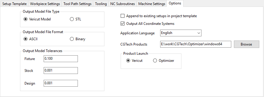
Use Output Model File Type to specify the type of model files that are created and passed to Vericut. Choose either Vericut Model (Vericut polygon file) or STL (Stereolithography model file). Use Output Model File Format to specify the file format of the model files. Choose either ASCII or Binary.
📝 NOTE: "Binary" Vericut/Optimizer polygon files are platform specific.
Use the Output Model Tolerance to specify tolerance values for Stock, Fixture, and Design models.
Gibbscam is a single setup product. If you wish to append the GibbsCAM part information to the setups that are already defined in your project template, you can click on the Append to existing setups in project template check-box. Otherwise, and more typically, the imported GibbsCAM part information will be the only setups in the generated project. If you wish to transfer all GibbsCAM part coordinate systems to Vericut/Optimizer, then you can click on the Output All Coordinate Systems check-box. The Application Language list allows for the selection of a native language.
CGTech Products allows you to change the directory used to launch Vericut/Optimizer from the interface. This directory is initialized by the CGTECH_PRODUCTS and CGTECH_VO_INSTALL environment variables. The Product Launch allows you to select to launch the desired application, Vericut or Optimizer
Generate and Run Vericut

When you have provided GibbsV with all the information it needs, you can perform the transfer of data to, and triggering of, Vericut. Click on the "Generate files" button to create the tool libraries, models and NC programs without triggering Vericut. Once you have all the files needed, you can fire up Vericut with the "Run Vericut" button. You can perform both of these steps at once with the "Generate and run" button. The dialog can be closed by pressing the  icon in the upper right hand corner of the dialog.
See Operations File in the Getting Started section of Vericut Help for information on the Operations File (or Ops File).
Preferences
Preferences File
GibbsV uses a preference file to save/restore default settings. The preference file is named gibbsv_version_user.prefs. The file will be saved on the HOMEDRIVE in the HOMEPATH. The preference file is read during GibbsV startup and written during GibbsV closing. The File Selection Box (FSB) filters are not user modifiable via the interface. The file filter tags are stored in the preference file and can be modified by the user. By default, 'Preferences' file is generated at C:\Users\username\gibbsv_version_user.prefs
Custom Data
The values that you set in any of the GibbsV windows are saved as part custom data in the GibbsCAM part file. When you re-open the GibbsCAM part file, the GibbsV settings are recalled as they were when you saved the file.
"Quick Start" training session
The GibbsCAM Interface "Quick Start" training sessions are designed to quickly teach a Vericut/Optimizer user the "basics" of using the GibbsCAM Interface. The download includes: CAD/CAM files, Vericut/Optimizer files, and step-by-step training sessions in PDF format.
Download: https://vericut.com/quick-start-training
📝 NOTE: to run the Quick Start files, GibbsCAM 2024 or later is required.