TDM Global Line
Location:
Tool Manager > Import tab > TDM Global Line
The TDM Global Line button opens the TDM Global Line Interface window enabling you to access this variant of the TDM Systems', Tool Data Management (TDM) system database.
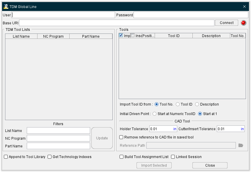
The TDM Global Line Interface enables users to connect to TDM’s product TDM Global Line and read in tool graphics and cutting data for use in simulations. TDM Global Line is TDM’s web service-based tool management system. The Interface reads TDM’s tool lists and creates 3D tool assemblies for use in simulations. Cutting data can also be read in from TDM Global Line during the import process for use in toolpath optimization within Tool Manager to run additional checks on your simulation.
User — Use to enter or TDM account ID.
Password — Use to enter your TDM account password. (NOTE: your password will not be saved in the .prefs file for when you reopen Optimizer to connect to TDM Global Line)
Base URl — Use to enter the web address for your TDM Global Line account. TDM Global Line could be in the cloud or installed locally.
Connect — Click on the Connect button to log into your TDM account. If there are any problems, an error message will display in the text field to the right of the Connect/Disconnect button.
The values you enter for User and Base URl are saved and automatically re-used the next time you enter this dialog.
📝 NOTE: A red light designates a connection is not made. A green light designates a connection is made to the database.
TDM Tool Lists — The TDM database will contain lists of tools that pertain to jobs or machines. When successful connection is made, the TDM Tool Lists table automatically populates with the available Tool Lists from TDM Global Line. To select such a list, you can specify a filter for the list names. If you do not enter a filter, all the lists will be placed in the table above, and there can be thousands.
Filters — Use the following filters to specify the tool lists that you want displayed in the Lists table. You can use "*" and "?" as wild cards in the filter (in the normal Optimizer manner) or use "%" as you would with TDM.
List Name — Use to enter a TDM list name to be used as a filter.
NC Program — Use to enter an NC program name to be used as a filter.
Part Name — Use to enter a Part name to be used as a filter.
Update — Click to Update the TDM Tool Lists displayed based if the filter criteria are used.
Pick the tool list that you need from the TDM Tool Lists table and the tools contained in that tool list will display in the Tools table.
The column headings in the Tools table correspond to the TDM field names, but the content of the Tool No. column gets used as the Tool ID in Tool Manager, and the TDM Tool ID and Description fields are combined to form the tool’s Description in Tool Manager.
Import — Toggle on (checked) to ensure that the selected tool is imported when Import is clicked.
Insert — Toggle on (checked) to import a tool so the cutter is defined as an insert (cutter) component. NOTE: for this option to work, TDM 3D tooling model needs to be created using specific steps. Contact Technical Support for more details.
Position — Uses the Position field from the Tool List of that specific tool to populate the Position column in the TDM Global Line Interface
Tool ID — Uses the Tool ID field of that specific tool to populate the Tool ID in Tool Manager
Description — Uses the Description field of that specific tool to populate the Tool ID in Tool Manager
Tool No — (Default) Uses the Tool No field of that specific tool to populate the Tool ID in Tool Manager
Import Tool ID from — Use this option to set what field from TDM Global line to be used to name the Tool ID in Tool Manager
Tool No — (Default) Uses the Tool No field of that specific tool from the TDM database to populate the Tool ID in Tool Manager
Tool ID — Uses the Tool ID field of that specific tool from the TDM database to populate the Tool ID in Tool Manager
Description — Uses the Description field of that specific tool from the TDM database to populate the Tool ID in Tool Manager
Initial Driven Point — Enables you to select between two choices (Start at Numeric ToolID and Start at 1). This is the same setting use in Tool Manager on the Utilities tab under Preferences. Changing the value in one location changes the setting in both settings.
Start at Numeric ToolID specifies that a Tool’s initial driven point will be named by their ToolID. Additional driven points will be named as described below for the Start at 1 option. The Start at Numeric ToolID feature only applies to numeric Tool IDs. Tools that have Alpha or Alphanumeric Tool IDs will be named as described below for the Start at 1 feature.
Start at 1 specifies that a Tool’s initial driven point will be named numerically starting with 1. Additional driven points will be named 2, 3, etc.
Holder Tolerance — Enables you to specify the Holder Tolerance by entering the tolerance value in the Holder Tolerance text field. The default value is read from the Tool Manager > Utilities ribbon > Preferences dialog.
Cutter/Insert Tolerance — Enables you to specify the Cutter/Insert Tolerance by entering the tolerance value in the Cutter/Tolerance text field. The default value is read from the Tool Manager > Utilities ribbon > Preferences dialog.
Remove reference to CAD file in saved tool — This feature is used to specify the format that the imported tool is to be saved in. When toggled "on" (checked), the default, the imported tool components are saved as Optimizer Polygon files. When toggled "off" (un-checked), the imported tool components are stored in the same CAD format that they were imported in. This feature is for TDM import only and the setting is saved in the project file.
Reference Path — Option to control where the .ply files from imported tools are stored.
-
If there is no .tls file saved/present prior to when tools are first imported, the .ply files by default go to the working directory.
-
If a .tls file is saved/present prior to when tools are imported, the .ply files default to the location of the .tls file (may not be the current working directory).
-
By default, the Reference Path field will not display a path until
 (Browse) is opened and a path is selected.
 -
If "Remove reference to CAD file in saved tool" is UNCHECKED, "Reference path" option is greyed out and not available (will reference where .stp files currently reside).
Append to Tool Library — When toggled on (checked), the Append to Tool Library option enables you to add the tools from the selected TDM list to those present in the currently accessed library. If there is a conflict between tool IDs, the tools already in the library will prevail. When this option is active, there will be no link between the project file and the TDM list, because the set of tools accessed by the project file is more comprehensive than the content of the TDM list.
Get Technology Index — when toggled on (checked), the Get Technology Indexes option enables you to access TDM’s technology Indexes (cutting limits and optimization settings) of tools to use in optimization of the NC Program. This option remains modal until changed by the user.
Build Tool Assignment List — When toggled on (checked) and there are tools with “TURRETINDEX” and “SPINDLE” defined in TDM a tool list will be built in the tool library file. A message “Tool list has been updated.” will be output to the Tool Manager logger after the import.
In cases where no matching tool component index is found with given turret index, the record in the assignment list will be shown as if it was a single channel/single turret system (no subsystem name). The tool list will be incorrectly built and the user is responsible correcting the problem.
Import Selected — Imports all of the selected tools into Tool Manager.
Close — Closes the TDM Interface window.
Saving the TDM Tooling Data for Use in a Vericut Simulation — There are two options to work with/save the TDM tool data for use in a simulation:
'Linked' session — No .tls file is saved. This option directly connects to the TDM database each time the simulation is opened/run to pull the tools from the selected, named TDM Tool List. If the connection cannot be established to the TDM database, the 3D cutting tools cannot be accessed or displayed.
📝 NOTE: This option only works with the tools as they are defined in TDM. No changes can be made to the tools in Tool Manager in any way. The following options in the TDM Interface will not be saved when working in a 'linked' mode.
Import column — no individual selected tools. All the tools in the TDM Tool List will be read into Tool Manager.
Insert column — no selections will be saved.
Append to Tool Library — toggled off (not checked) is default.
Build Tool Assignment List — toggled off (not checked) is default.
Linked Session — toggled off (not checked) is default.
Remove reference to CAD file in saved tool — toggled on (checked) is default.
To save a 'linked' session, click the X in the upper right corner of the Tool Manager window without saving the .tls file to a location.
The TDM Tool List name will also appear in the Project Tree as shown below:

When reopening Tool Manager, the 'referenced' TDM list will display in the Tool Manager's title bar. The Link Session option remains modal until changed by the user.
Saved .tls file — .tls file is created and saved. This option creates a copy of the 3D tool(s) for use in the simulation and stores the tooling data and information in a .tls file. If changes are made to the tools in the TDM Tool List, the list will need to be read into Tool Manager again. All above options (Import/Insert column, Append to Tool Library, Build Tool Assignment List, Remove references to CAD file in saved tool, and any ‘manual’ changes to tools) will apply and be saved accordingly.
To save the .tls file, click the Save File icon from the Tools tab.